Battery protection circuit
A technology for protecting circuits and batteries, applied in battery overcharge protection, battery circuit devices, battery overdischarge protection, etc., can solve the problems of power consumption, large loop resistance, poor reversibility of secondary protection circuits, etc.
- Summary
- Abstract
- Description
- Claims
- Application Information
AI Technical Summary
Problems solved by technology
Method used
Image


Examples
Embodiment approach
[0044] like Figure 5 As shown, the controllable switch 4 is an N-type MOS transistor, including G pole, S pole and D pole, the S pole of the controllable switch 4 is connected to the negative terminal 6, and the D pole is connected to the positive terminal 5, The G pole is connected to the control module 21. When the control module 21 inputs a control signal, the current from the D pole to the S pole is turned on, that is, the current from the positive terminal 5 to the negative terminal 6 is turned on.
[0045] like Image 6 As shown, the controllable switch 4 is a P-type MOS tube, including G pole, S pole and D pole, the S pole of the controllable switch 4 is connected to the positive terminal 5, and the D pole is connected to the negative terminal 6, The G pole is connected to the control module 21. When the control module 21 inputs a control signal, the current from the S pole to the D pole is turned on, that is, the current from the positive terminal 5 to the negative t...
Embodiment 1
[0055] The battery protection circuit disclosed by the invention can be set as a secondary protection circuit.
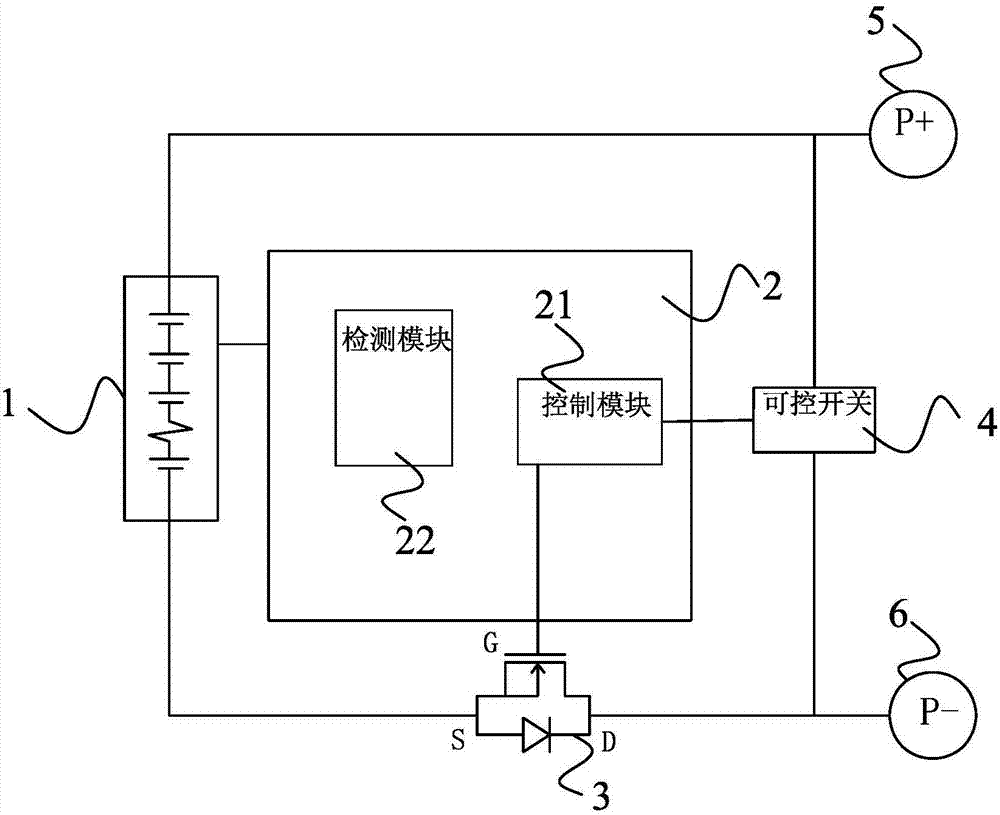
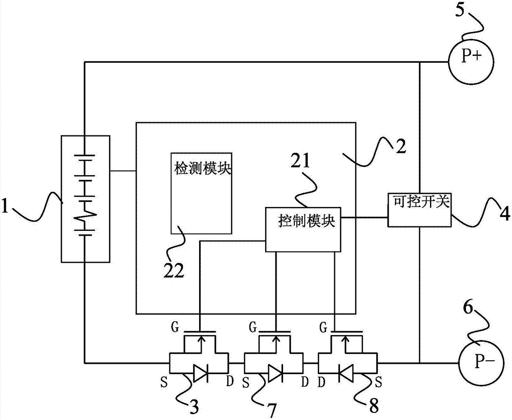
[0056] see figure 2 As shown, in this embodiment, a battery protection circuit is disclosed, which consists of a battery pack 1, a BMS main control unit 2, a charging MOS tube 8, a first discharging MOS tube 3, a second discharging MOS tube 7, a controllable switch 4. Positive terminal 5 and negative terminal 6 constitute;
[0057] The first discharge MOS transistor 3 is connected in series with the battery pack 1 between the positive terminal 5 and the negative terminal 6, and the first discharge MOS transistor 3 is used to control the on-off of the output current of the battery pack 1;
[0058] Both ends of the controllable switch 4 are connected between the positive terminal 5 and the negative terminal 6, and the series circuit composed of the battery pack 1 and the first discharge MOS transistor 3 is connected in parallel with the controllable switch 4, the T...
Embodiment 2
[0070] see Figure 4 As shown, this embodiment discloses a battery protection circuit, most of the implementation of the battery protection circuit is the same as that of Embodiment 1, the difference lies in:
[0071] The battery protection circuit also includes a current detection resistor 9, which is connected in series with the battery pack 1 to obtain the current flowing through the current detection resistor 9; the detection module 22 includes a current analog-to-digital converter 222, The current analog-to-digital converter 222 is preferably a fuel gauge; the current analog-to-digital converter 222 is connected to the current detection resistor 9 and the control module 21 respectively, and is used to convert the obtained current analog signal into a current digital signal, and convert the obtained current analog signal to a current digital signal. The current digital signal is transmitted to the control module 21.
[0072] The battery protection circuit also includes a ...
PUM
 Abstract
Description
Claims
Application Information
 - R&D
- Intellectual Property
- Life Sciences
- Materials
- Tech Scout
- Unparalleled Data Quality
- Higher Quality Content
- 60% Fewer Hallucinations
Browse by: Latest US Patents, China's latest patents, Technical Efficacy Thesaurus, Application Domain, Technology Topic, Popular Technical Reports.
© 2025 PatSnap. All rights reserved.Legal|Privacy policy|Modern Slavery Act Transparency Statement|Sitemap|About US| Contact US: help@patsnap.com