Diffusion furnace for silicon wafers for solar cells capable of relieving residual thermal stress
A technology for solar cells and residual thermal stress, which is applied in the directions of post-processing, diffusion/doping, and crystal growth, and can solve problems such as fracture, silicon chip damage, and thermal stress that are difficult to eliminate
- Summary
- Abstract
- Description
- Claims
- Application Information
AI Technical Summary
Problems solved by technology
Method used
Image
Examples
Embodiment 1
[0024] Such as figure 1 A silicon wafer diffusion furnace for solar cells that can realize residual thermal stress relief treatment is shown, which includes a furnace body 1, which is provided with an air inlet pipe 2 and an exhaust gas pipe leading from the outside to the inside of the furnace body 1. The pipeline 3 is provided with an exhaust fan 4 above the exhaust pipeline 3; the inside of the furnace body 1 is provided with a quartz boat 5 for placing silicon wafers; A furnace door 6 is provided, and a heat dissipation pipe 7 extending toward the outside of the furnace body 1 is provided between the edge of the placement end surface 101 and the furnace door 6; in the furnace body 1, an exhaust pipe 3 is provided with A plurality of heat dissipation ports 8 lead to the heat dissipation pipe 7 , and the plurality of heat dissipation ports 8 are evenly distributed along the axial direction of the heat dissipation pipe 7 .
[0025] As an improvement of the present invention,...
Embodiment 2
[0029] As an improvement of the present invention, such as figure 1 As shown, in the heat dissipation pipe 7, a flow guide end body 11 is respectively arranged between any two adjacent heat dissipation ports 8, and the flow guide end body 11 extends in a ring along the inner wall of the heat dissipation pipe 7, and the flow guide end body 11 The side end surfaces in the axial direction of the heat dissipation pipe 7 all adopt a curved surface structure that bends toward the inside of the guide end body 11 . By adopting the above-mentioned technical scheme, it can guide the flow direction of the air flow output by the heat dissipation port through the arrangement of the flow guide end body, so that the air flow output by each heat dissipation port can flow between the two adjacent flow guide end bodies. Under the action of the curved surface structure, a circulation with a relatively fixed range of motion is formed in its corresponding area, so that the corresponding position o...
Embodiment 3
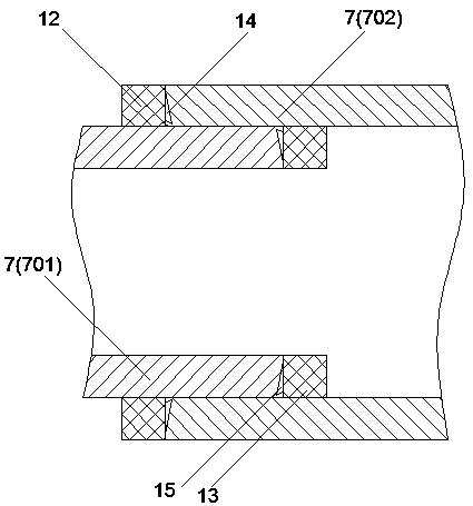
[0032] As an improvement of the present invention, such as figure 2 As shown, the heat dissipation pipeline 7 includes a first pipeline 701 connected to the end surface 101 of the furnace body 1, and a second pipeline 702 arranged at the end of the first pipeline 701; the length of the first pipeline 701 is 15 cm, the end of the first pipeline 701 is provided with an external thread, the end of the second pipeline 702 is provided with an internal thread, and the first pipeline 701 and the second pipeline 702 are connected by threads; the first pipeline 701 A first fixed end body 12 opposite to the end of the second pipe 702 is arranged on the outer wall, and a first tooth body 14 is arranged on the opposite end surface of the first fixed end body 12 and the second pipe 702. The first tooth body 14 and the second pipe 702 are engaged with each other, the inner wall of the second pipe 702 is provided with a second fixed end body 13 opposite to the end of the first pipe 701, the...
PUM
| Property | Measurement | Unit |
|---|---|---|
| length | aaaaa | aaaaa |
Abstract
Description
Claims
Application Information
 - R&D
- Intellectual Property
- Life Sciences
- Materials
- Tech Scout
- Unparalleled Data Quality
- Higher Quality Content
- 60% Fewer Hallucinations
Browse by: Latest US Patents, China's latest patents, Technical Efficacy Thesaurus, Application Domain, Technology Topic, Popular Technical Reports.
© 2025 PatSnap. All rights reserved.Legal|Privacy policy|Modern Slavery Act Transparency Statement|Sitemap|About US| Contact US: help@patsnap.com


