
Particle classification device and method thereof

A particle classification and particle technology, applied in chemical instruments and methods, solid separation, separating solids from solids with airflow, etc., can solve the problem of complex structure of wind eddy current classifier, inconvenient adjustment of cutting particle size, cutting particle size Inconvenient adjustment and other problems to achieve the effect of weakening mutual interference/coercion, reducing pressure drop, and low degree of back mixing

Inactive Publication Date: 2017-09-22
DALIAN UNIV OF TECH
View PDF8 Cites 6 Cited by
  • Summary
  • Abstract
  • Description
  • Claims
  • Application Information

AI Technical Summary

Problems solved by technology

The main evaluation indicators of particle classification include classification efficiency, classification accuracy and cutting particle size, etc.; classification methods can be roughly divided into two types: screening and airflow classification. Airflow classification has unique advantages for the occasions of viscous, high temperature, small particle size particle classification, etc. Advantages; airflow classification produces different motion trajectories according to the drag force, centrifugal force, gravity, inertial effect, etc. of particles with different particle sizes / density in the fluid, so as to realize particle classification with different particle sizes / density; airflow classification is according to the classifier Whether there are moving parts can be divided into static classification and dynamic classification; dynamic classifier mainly refers to various turbine classifiers, which have high classification accuracy and convenient adjustment of cutting particle size, but the equipment structure is complex and energy consumption is high; traditional static classification mainly Including inertial classification, cyclone classification, gravity classification and other technologies and their combinations, this type of classifier has simple structure, low operating cost, convenient operation and maintenance, but the classification accuracy is low and the cutting particle size adjustment is inconvenient
CN201320499Y discloses a cyclone separator particle size separation device, the upper part of which is in the shape of a cylinder and the lower part is in the shape of an inverted cone. When solid particles of different particle sizes are used to rotate under the action of centrifugal force, fine materials are more likely to move to the center of the cylinder. Through unique design The internal and external cavity structure realizes the classification of coarse and fine materials. This device only introduces the internal and external cavity structure on the basis of the traditional cyclone separator. The structure is simple, but the classification efficiency is closely related to the air intake, and the cutting particle size is inconvenient to adjust
CN2625062Y discloses a wind-force vortex classifier, which is mainly composed of a volute body and classifiers respectively arranged on both sides of the body. The coarse and heavy particles are thrown out and collected along the tangential direction of the vortex by using physical differences such as the particle size and density of the powder in the airflow. The small and light dust is discharged from the volute from the center of the vortex by the suction force of the fan, and discharged along the air outlet on the classifier. A movable guide device is installed on the volute body to adjust the cutting particle size of the coarse and fine particles. The wind vortex classifier The structure is complex, and the setting of the adjustable flow guiding device also brings about the sealing problem of the volute casing

Method used


Image

  • Particle classification device and method thereof
  • Particle classification device and method thereof

Examples


Embodiment

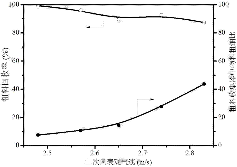
[0025] The particle classification device used in the experiment includes a cyclone separator 2, a sedimentation classifier 6, a coarse / heavy particle group collector 4 and a fine / light particle group collector 5; the top of the cyclone separator 2 cylinder is connected to the tail air outlet pipe through a cone 1, the inlet end does not extend into the cyclone separator 2, the outlet end of the tail air outlet pipe 1 is connected to the fine / light particle group collector 5, and the lower part of the cyclone separator 2 cylinder is provided with a primary air inlet pipe 3. The bottom of the cyclone separator 2 is a cone structure, which is connected to the top of the sedimentation classifier 6; the height-diameter ratio of the sedimentation classifier 6 is 20:1, and the bottom of the sedimentation classifier 6 is connected to the coarse / heavy particle The heavy particle group collector 4 is provided with a secondary air intake pipe 7 .

[0026] A mixture of 20-40 mesh and 60-...


PUM


Abstract

The invention belongs to the technical field of powder processing and utilizing and provides a particle classification device and a method thereof. The middle of the top of a barrel body of a cyclone separator is connected with the inlet end of a tail air outlet pipe, and the inlet end does not stretch into the cyclone separator; the outlet end of the tail air outlet pipe is connected with a fine / light particle set collector; the lower middle portion of the barrel body of the cyclone separator is provided with a primary air inlet pipe; the bottom of the barrel body of the cyclone separator is of a conical structure, and is connected with the top of a sedimentation classifier; the bottom of the sedimentation classifier is connected with a coarse / heavy particle set collector; and the lower portion of the sedimentation classifier or the coarse / heavy particle set collector is provided with a secondary air inlet pipe. Based on the differences of the centrifugal forces and the terminal speeds of coarse / heavy particles and fine / light particles in mixed particle size / density particle materials, the air speeds of primary air and secondary air are adjusted, it can be achieved that the cutting particle size is flexibly adjusted and changed, and the classification precision is high; and operation is easy and convenient, the structure is simple, and the particle classification device and the method thereof can be applied to the normal temperature / high temperature particle classification environment.

Description

technical field [0001] The invention belongs to the technical field of powder processing and utilization, and relates to the classification / separation operation of mixed particle diameter / density solid particles. Background technique [0002] Solid particle classification technology is widely used in many industrial processes, such as ore and sand in mineral processing, clean coal and coal gangue in coal preparation, coal ash fusion separation in coal gasification, particle screening in the pharmaceutical industry, and classification and classification of agricultural materials. Separation etc. The main evaluation indicators of particle classification include classification efficiency, classification accuracy and cutting particle size, etc.; classification methods can be roughly divided into two types: screening and airflow classification. Airflow classification has unique advantages for the occasions of viscous, high temperature, small particle size particle classification,...

Claims


Application Information

Patent Timeline
Patent Type & Authority Applications(China)
IPC IPC(8): B07B9/02
Inventor 徐绍平王光永王超
Owner DALIAN UNIV OF TECH
Learn More