
Integrated substrate chamber millimeter wave array antenna

A technology of substrate integration and array antenna, which is applied in the direction of antenna, antenna array, antenna grounding switch structure connection, etc., can solve the problem of low gain of millimeter wave array antenna, and achieve the effect of increasing bandwidth, increasing electrical length, and increasing gain

Active Publication Date: 2017-09-12
HUAZHONG UNIV OF SCI & TECH
View PDF1 Cites 7 Cited by
  • Summary
  • Abstract
  • Description
  • Claims
  • Application Information

AI Technical Summary

Problems solved by technology

[0005] In view of the above-mentioned defects, the object of the present invention is to provide a substrate-integrated cavity millimeter-wave array antenna, which aims to solve the technical problem of low gain of the existing millimeter-wave array antenna

Method used


Image

  • Integrated substrate chamber millimeter wave array antenna
  • Integrated substrate chamber millimeter wave array antenna
  • Integrated substrate chamber millimeter wave array antenna

Examples


Embodiment Construction

[0027] In order to make the object, technical solution and advantages of the present invention clearer, the present invention will be further described in detail below in conjunction with the accompanying drawings and embodiments. It should be understood that the specific embodiments described here are only used to explain the present invention, not to limit the present invention.

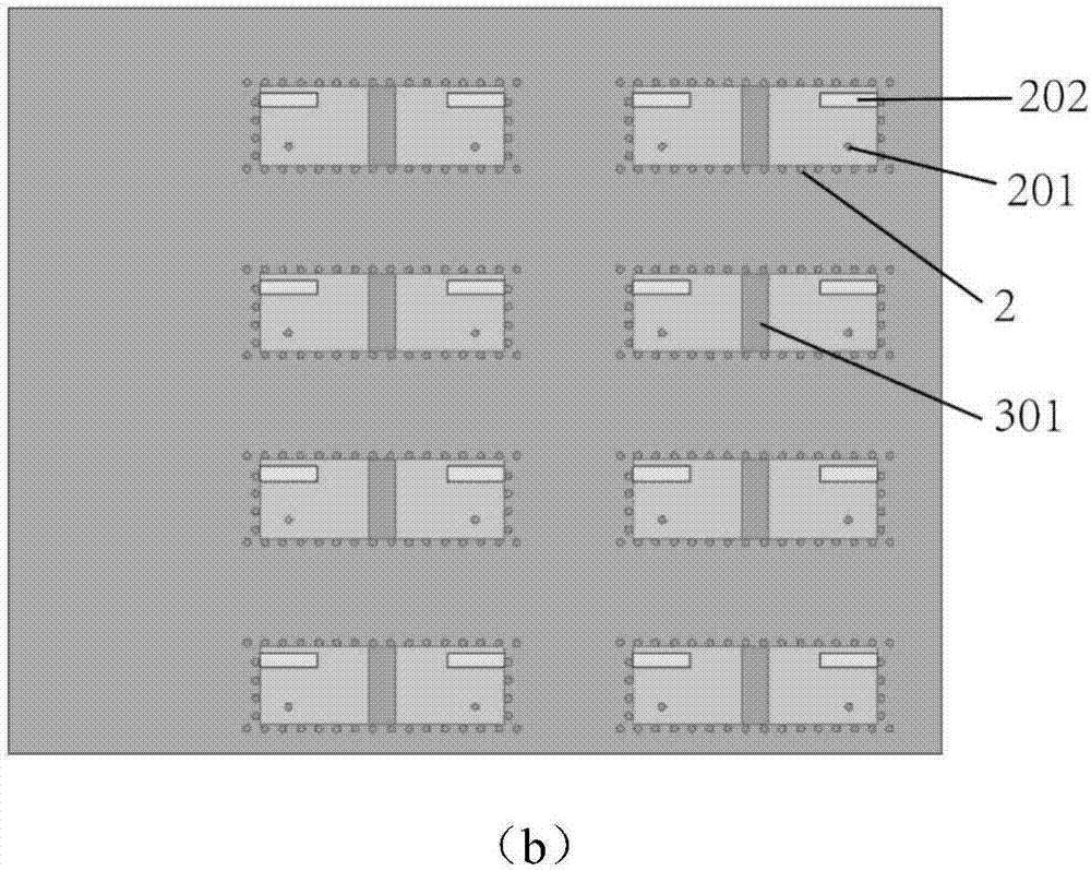
[0028] figure 1 It is a structural schematic diagram of an embodiment of the substrate-integrated cavity millimeter-wave array antenna provided by the present invention. The substrate-integrated cavity millimeter-wave array antenna includes an external transfer module 5, a power dividing module and an antenna array.

[0029] The external transfer module 5 is made of three layers (that is, the fourteenth to the sixteenth layers) of LTCC cast sheets laminated, and a three-layer SIC is surrounded by metal through-hole columns. The cavity size is 2.3mm×1mm. There is a lower feeding hole 501 with a si...


PUM


Abstract

The invention discloses an integrated substrate chamber millimeter wave array antenna. The antenna comprises an antenna array, a power division module and an external switching module, wherein the external switching module is used for leading electromagnetic waves from metal waveguide to the power division module, the electromagnetic waves are divided by the power division module into multiple paths of electromagnetic waves for output, the electromagnetic waves enter into an integrated substrate chamber of an antenna unit, high-order mode resonance is generated in the integrated substrate chamber through expanding a radiation aperture of the integrated substrate chamber, gain of the millimeter wave array antenna is improved, high-order mode field distribution of the electromagnetic waves in the integrated substrate chamber is adjusted through a parasitic structure, so the high-order mode radiation direction of the electromagnetic waves in the integrated substrate chamber is turned to be in a normal direction of the integrated substrate chamber, and normal operation of the antenna array is realized, moreover, the parasitic structure employs an I-like metal sheet, current length of the metal sheet can be improved, and bandwidth of the antenna array is enhanced.

Description

technical field [0001] The invention belongs to the technical field of millimeter-wave antennas, and in particular relates to a substrate-integrated cavity millimeter-wave array antenna. Background technique [0002] With the continuous development of communication technology, the spectrum resources of traditional microwave frequency bands are increasingly tight. In order to alleviate this problem, people have gradually shifted their attention to the millimeter wave frequency band with a higher frequency band. Millimeter wave has attracted extensive attention due to its short wavelength, wide frequency bandwidth, and fast transmission rate. In a wireless communication system, the transmission and reception of the radio must rely on the antenna. As a key component in the millimeter wave communication system, the millimeter wave antenna has a crucial impact on the final performance of the system. However, since the millimeter wave has a large attenuation when propagating in...

Claims


Application Information

Patent Timeline
IPC IPC(8): H01Q1/38H01Q1/50H01Q21/00
CPCH01Q1/38H01Q1/50H01Q21/00
Inventor 王晓川于晨武楼熠辉吕文中范桂芬
Owner HUAZHONG UNIV OF SCI & TECH
Learn More