Photovoltaic mosquito killer lamp

A mosquito-killing lamp and photovoltaic technology, which is applied to light sources, electric light sources, and devices for capturing or killing insects, etc., can solve the problem of poor effect of stick-catching mosquito-killing lamps, high power consumption of airflow mosquito-absorbing lamps, and difficulty in mosquito-killing lamps. Promotion and other issues, to achieve the effect of increasing lighting functions, solving outdoor power supply problems, and simple structure

Inactive Publication Date: 2017-09-12
叶其峰
View PDF0 Cites 0 Cited by
  • Summary
  • Abstract
  • Description
  • Claims
  • Application Information

AI Technical Summary

Problems solved by technology

However, the poor effect of the sticky mosquito killer lamp and the high power consumption of the airflow mosquito killer lamp make it difficult to popularize the mosquito killer lamp
Similarly, electronic mosquito killer lamps are limited by power supply
In particular, it is very inconvenient to hang the mosquito killer outdoors and need to pull the wires outdoors

Method used


Image

  • Photovoltaic mosquito killer lamp
  • Photovoltaic mosquito killer lamp
  • Photovoltaic mosquito killer lamp

Examples


Embodiment 1

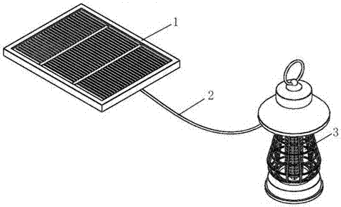
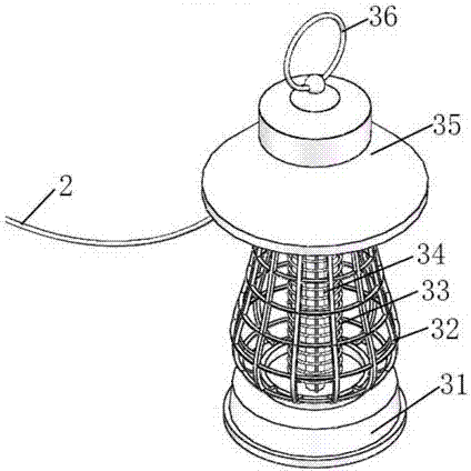
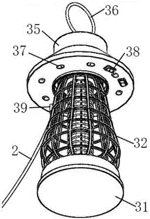
[0020] Such as Figure 1 to Figure 4 As shown, the photovoltaic mosquito killing lamp of this embodiment includes a photovoltaic power generation panel 1, a connecting line 2 and a mosquito killing lamp 3, and the photovoltaic power generation panel 1 is connected to the mosquito killing lamp 3 through a connecting line 2, and is characterized in that: Mosquito killer lamp 3 is made of base 31, protective cover 32, high-voltage electric shock net 33, light pipe group 34 and head cover 35, and described protective cover 32, high-voltage electric shock net 33 and light pipe group 34 are located at base 31 and head cover 35, a high-voltage electric shock net 33 is provided on the periphery of the light pipe group 34, a protective cover 32 is provided on the periphery of the high-voltage electric shock net 33, a suspension ring 36 is provided above the head cover 35, and an LED lamp is provided at the bottom Group 37, switch 38 and USB interface 39 are equipped with a battery and ...

Embodiment 2

[0029] The photovoltaic mosquito killing lamp of this embodiment includes a photovoltaic power generation panel 1, a connecting wire 2 and a mosquito killing lamp 3, and the photovoltaic power generation board 1 is connected to the mosquito killing lamp 3 through a connecting wire 2, and is characterized in that: the described mosquito killing lamp Lamp 3 is a suction type mosquito killer lamp.

[0030] The suction-type mosquito killer lamp sucks the mosquitoes into the container through the fan, and then air-dries them to death. This way of killing mosquitoes is very environmentally friendly, healthy and safe.


PUM


Abstract

The invention discloses a photovoltaic mosquito killer lamp. The photovoltaic mosquito killer lamp comprises a photovoltaic power generation panel, a connecting wire and a mosquito killer lamp, wherein the photovoltaic power generation panel is connected with the mosquito killer lamp through the connecting wire. The photovoltaic mosquito killer lamp is characterized in that the mosquito killer lamp consists of a base, a protective cover, a high-voltage shock net, a light tube set and a head cap, wherein the protective cover, the high-voltage shock net and the light tube set are arranged between the base and the head cap. The photovoltaic mosquito killer lamp is simple in structure and convenient to use; the mosquito killer lamp is powered up by the photovoltaic power generation panel, so that the mosquito killer lamp can work continuously without restriction from outdoor power supply conditions, outdoor power supply is effectively realized, and photovoltaic power supply meets the energy saving and environmental protection requirements; as LED lamp sets and ultraviolet fluorescent tubes are arranged, the working state of lighting or fluorescent mosquito luring and killing can be manually switched by switches, and the mosquito killer lamp is additionally endowed with the lighting function; as the USB connecting wire is arranged, plugging is convenient; and as a lithium battery is adopted, repeatedly charging can be realized.

Description

technical field [0001] The invention relates to a mosquito lamp, especially a photovoltaic mosquito killer lamp, and belongs to the technical field. Background technique [0002] The mosquito killing lamp is a mosquito killing device that does not need to use any chemical mosquito killing substances. It is a new generation of high-efficiency and environmentally friendly mosquito killing equipment that absorbs foreign advanced technology and undergoes multiple technical improvements. An environmentally friendly, non-polluting and efficient killing tool developed by using mosquitoes’ habit of phototaxis, moving with airflow, temperature sensitivity, and gregariousness, especially chasing carbon dioxide breath and sex pheromone, also called black light mosquito killing tool . The mosquito killer has the characteristics of simple structure, low price, elegant appearance, small size and low power consumption. Since it does not need to use any chemical mosquito killing substance...

Claims


Application Information

Patent Timeline
Patent Type & Authority Applications(China)
IPC IPC(8): A01M1/04A01M1/22A01M1/08H02J7/35F21S9/03F21V23/04F21Y115/10
CPCA01M1/04A01M1/08A01M1/223F21S9/032F21V23/04F21Y2115/10H02J7/00H02J7/35Y02B20/72
Inventor 叶其峰
Owner 叶其峰
Why Eureka
Try Eureka