
Multistage separation technology and device

A multi-stage separation and stage separation technology, which is applied in the fields of oil and gas and sewage treatment, can solve problems such as increased difficulty, poor separation effect of three-phase separators, and incompatible operating parameters, so as to reduce manufacturing and management operating costs, reduce Equipment safety management risk, achieve the effect of modularization

Active Publication Date: 2017-08-29
西安长庆油气建设实业有限责任公司
View PDF3 Cites 5 Cited by
  • Summary
  • Abstract
  • Description
  • Claims
  • Application Information

AI Technical Summary

Problems solved by technology

[0002] As most of my country's oilfields gradually enter the mid-to-late stage of exploitation, the water content of crude oil continues to increase. On the one hand, the amount of produced fluid and sewage treatment increases sharply. Some process equipment in the gathering and transportation system cannot meet the production requirements. The water content and total liquid volume of heated crude oil increase, resulting in a substantial increase in energy consumption for production; In particular, the difficulty of sewage treatment has increased sharply, which puts forward higher requirements for oil, gas and water solids treatment equipment
In addition, with the development and production of oilfields, the original separators in each station cannot meet the actual changes due to their design conditions and operating parameters, and it is difficult to meet the oil and water separation requirements
Judging from the current use of three-phase separators in various domestic oilfields, due to the obvious lack of theory and experience in designing three-phase separators, coupled with differences in national conditions and factory manufacturing, the actual operating parameters of the three-phase separators often differ from those provided by the site. Incompatibility, coupled with the influence of the deposition of solid particles in the liquid in the stable section, leads to poor separation effect of the three-phase separator, and many three-phase separators are useless

Method used


Image

  • Multistage separation technology and device

Examples


Embodiment 1

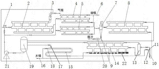
[0027] In order to overcome the deficiencies of the prior art, the present embodiment provides a multi-stage separation process, which at least includes the following steps:

[0028] Step 1) Separation of the primary separation pipe: the incoming liquid enters the primary separation pipe 2 from the liquid inlet pipe 1, and after rapid dynamic separation, the associated gas enters the gas-liquid separator 3 for gas-liquid separation, and the separated gas passes through the gas outlet pipe For external transport, the liquid separated by the primary separation pipe 2 enters the upper pipe group 4 of the secondary separation pipe and the lower pipe group 5 of the secondary separation pipe;

[0029] Step 2) double separation of the secondary separation tube: the liquid entering the upper tube group 4 of the secondary separation tube and the lower tube group 5 of the secondary separation tube is separated at the same time, the upper tube group 4 of the secondary separation tube and ...

Embodiment 2

[0039] This embodiment provides a figure 1The multi-stage separation device shown includes a liquid inlet pipe 1, which is characterized in that: the liquid inlet pipe 1 is connected to the inlet of the first-stage separation pipe 2, and the upper outlet of the first-stage separation pipe 2 is connected to a gas-liquid separator 3 , the lower outlet of the primary separation tube 2 is connected to the inlet of the upper tube group 4 of the secondary separation tube and the inlet of the lower tube group 5 of the secondary separation tube, the upper tube group 4 of the secondary separation tube and the lower tube of the secondary separation tube Group 5 is connected in parallel, the upper outlets of the upper tube group 4 of the secondary separation tube and the lower tube group 5 of the secondary separation tube are connected to the oil outlet pipeline 6, the upper tube group 4 of the secondary separation tube and the lower tube group 5 of the secondary separation tube The lowe...

Embodiment 3

[0043] On the basis of embodiment 2, this embodiment provides a kind of figure 1 In the multi-stage separation device shown, the inlet end of the four-stage separation pipe 14 is also provided with an aeration head 22 , and the gas outlet of the gas-liquid separator 3 is connected to the aeration head 22 . The gas from the gas-liquid separator 3 enters the aeration head 22 in the four-stage separation pipe 14, and performs air flotation separation on the oil and water in the four-stage separation pipe 14 to further ensure the separation effect. With this structure, the aeration process Completed in a sealed room, it has the characteristics of good safety and easy management.

[0044] Further, in order to ensure the separation effect and safety, the first-stage separation pipe 2, the upper pipe group 4 of the second-stage separation pipe, the lower pipe group 5 of the second-stage separation pipe, the third-stage separation pipe 8 and the fourth-stage separation pipe 14 all inc...


PUM


Abstract

The invention provides a multistage separation technology. Oil, gas, water and solids are separated through primary separation of a separating tube, secondary double separation of the separating tube, liquid-solid separation, third separation of the separating tube, primary cyclone separation, secondary cyclone separation, fourth separation of the separating tube, settling separation and cycling. A multistage separation device comprises a primary separating tube, an upper tube unit of a secondary separating tube, a lower tube unit of the secondary separating tube, a liquid-solid separator, a third separating tube, a cyclone I, a cyclone II, a fourth separating tube, a settling tube and a liquid storage tank. Oil, gas, water and solids are quickly separated by means of the characteristics of the pipeline, the density difference of phase media and dynamic separation, a conventional method of separating multiple phases by means of a container is broken through, an explosion failure mode of the pressure container is converted into a leakage failure model of the pressure pipeline, so that the safety management risk of equipment is greatly reduced.

Description

technical field [0001] The invention relates to separation equipment in the field of oil and gas and sewage treatment, in particular to a multi-stage separation process and device. Background technique [0002] As most of my country's oilfields gradually enter the mid-to-late stage of exploitation, the water content of crude oil continues to increase. On the one hand, the amount of produced fluid and sewage treatment increases sharply. Some process equipment in the gathering and transportation system cannot meet the production requirements. The water content and total liquid volume of heated crude oil increase, resulting in a substantial increase in energy consumption for production; In particular, the difficulty of sewage treatment has increased sharply, which puts forward higher requirements for oil, gas and water solids treatment equipment. In addition, with the development and production of oilfields, the original separators in each station cannot meet the actual changes ...

Claims


Application Information

Patent Timeline
IPC IPC(8): C02F9/02C10G53/02C10L3/10E21B43/34
CPCC02F1/24C02F1/38C02F1/40C02F1/52C02F9/00C02F2001/007C02F2301/08C10G53/02C10L3/10C10L3/101E21B43/34
Inventor 郑生宏杨仁强何茂林刘丰宁闫怀荣蒋真友钟兴福张军史仕荧张昊任泉龙贺建国许丽樊勇毛勇蒋勇
Owner 西安长庆油气建设实业有限责任公司
Learn More