
Three-dimensional infinite element artificial boundary establishment method suitable for explicit analysis

A building method, a three-dimensional technology, applied in 3D modeling, special data processing applications, image data processing, etc., can solve the problems of time-consuming calculation, difficult to achieve convergence, unable to set grounding spring-damper, etc., to achieve computational efficiency High and efficient effect

Inactive Publication Date: 2017-08-25
SUN YAT SEN UNIV
View PDF4 Cites 2 Cited by
  • Summary
  • Abstract
  • Description
  • Claims
  • Application Information

AI Technical Summary

Problems solved by technology

This method can be implemented in the implicit dynamic analysis of ABAQUS, but for large and complex 3D structural models that need to consider the influence of nonlinear factors, it is difficult to achieve convergence when using implicit dynamic analysis calculations, and the calculation is time-consuming, and ABAQUS explicit analysis can improve calculation efficiency while ensuring calculation stability, but it is limited by the inability to set ground spring-damper in explicit dynamic analysis, which affects the realization of viscoelastic artificial boundary in explicit dynamic analysis.

Method used


Image

  • Three-dimensional infinite element artificial boundary establishment method suitable for explicit analysis
  • Three-dimensional infinite element artificial boundary establishment method suitable for explicit analysis
  • Three-dimensional infinite element artificial boundary establishment method suitable for explicit analysis

Examples


Embodiment 1

[0046] Example 1: Calculation of Artificial Boundary Dynamics of 3D Soil

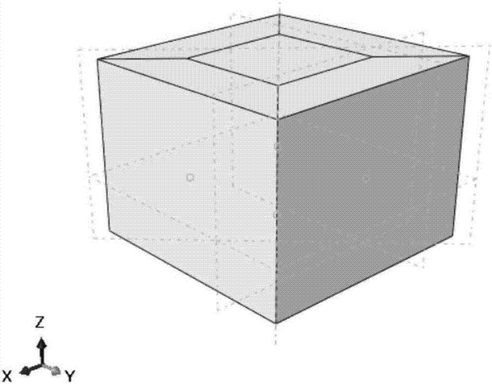
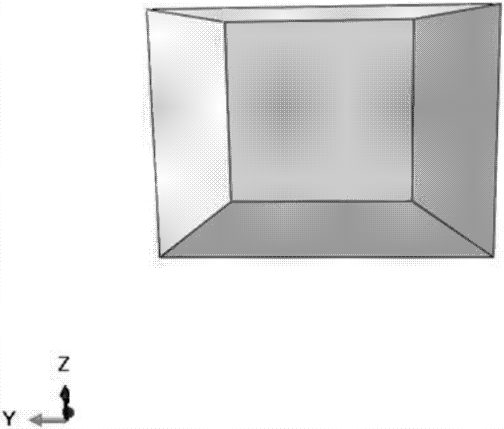
[0047] Such as figure 2 As shown, the geometric range of the intercepted soil is 400m×400m×300m by adopting the three-dimensional soil model for analysis, and the geometric size of the finite element near-field area of ​​the intermediate soil is: 200m×200m×200m, and the grid unit type of this part is used C3D8R finite element simulation, and the outer areas of the four sides and the bottom of the finite element soil such as image 3 , 4 The simulation is shown using the infinite element CIN3D8 unit. The material parameter characteristics of the soil are: density ρ=2500kg / m 3 , elastic modulus E = 14.82GPa, Poisson's ratio ν = 0.3, shear wave velocity C s =1510m / s, compression wave velocity C p =2825m / s. Input a quarter of the sinusoidal displacement wave of vertical incidence, the duration is taken as 1s, its expression is: when 0≤t≤0.25s, u(t)=0.01sin(4πt), and the displacement at other times is...

Embodiment 2

[0048] Example 2: Calculation of artificial boundary dynamics of three-dimensional soil under seismic wave load

[0049] Using the soil model in Example 1, input the vertically incident unidirectional LBNS seismic wave, the acceleration time history is as follows Figure 8 As shown, the duration is 30s, the acceleration is in the unit of gravitational acceleration g, and the peak value of the acceleration is 0.1g. Convert it into an equivalent load and apply it to the nodes at the interface between the finite element and the infinite element. Taking the top surface of the soil, that is, the center point of the upper surface, as the observation point, the acceleration time-history response is calculated as follows: Figure 9 As shown in , it is only necessary to observe whether the obtained acceleration response peak value of the center point of the soil free surface satisfies the nearly twice relationship with the input seismic wave peak value. It is found that the obtained ...


PUM


Abstract

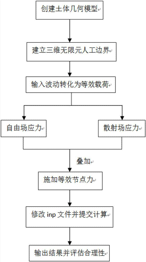
The invention relates to a three-dimensional infinite element artificial boundary establishment method suitable for explicit analysis. The method comprises the following steps that: S1: creating a three-dimensional soil mass geometric model, then, intercepting parts of soil mass from the three-dimensional soil mass geometric model to serve as a near-field area, and taking the residual soil mass as a far-field area; S2: establishing a three-dimensional infinite element artificial boundary, using the infinite element to simulate the far-field area, and adopting a finite element to simulate the near-field area; and S3: converting external source fluctuation into equivalent nodal force, and then, applying the nodal force to the node of the constructed artificial boundary.

Description

technical field [0001] The invention relates to the field of anti-seismic analysis, in particular to a three-dimensional infinite element artificial boundary establishment method suitable for explicit analysis. Background technique [0002] Analyzing a structure's response to earthquakes is an important part of assessing the safety and integrity of a structure. The seismic analysis of a structure is affected by factors such as structure, ground motion, site soil properties, etc., and the structural system connected to the foundation often has the characteristics of high stiffness compared with the foundation. At this time, the assumption of a rigid foundation cannot reflect the real structure. response, so the influence of soil-structure interaction needs to be considered in the research. [0003] Soil-structure interaction is caused by the deformation caused by the different material properties of the foundation soil and the structure, resulting in the interaction between ...

Claims


Application Information

Patent Timeline
Patent Type & Authority Applications(China)
IPC IPC(8): G06F17/50G06T17/20
CPCG06T17/20G06F30/23G06F30/20
Inventor 刘玉岚兀琼
Owner SUN YAT SEN UNIV
Learn More