Control circuit of two-way DC/DC (Direct Current/Direct Current) power converter and control method of control circuit
A technology of power converter and control circuit, which is applied in the direction of DC power input conversion to DC power output, output power conversion device, control/regulation system, etc., and can solve the problems of poor dynamic performance of bidirectional DC/DC power converters, etc.
- Summary
- Abstract
- Description
- Claims
- Application Information
AI Technical Summary
Problems solved by technology
Method used
Image
Examples
Embodiment 1
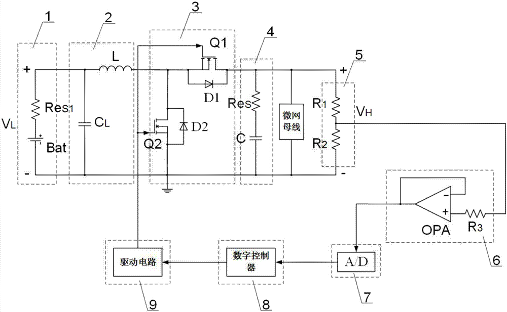
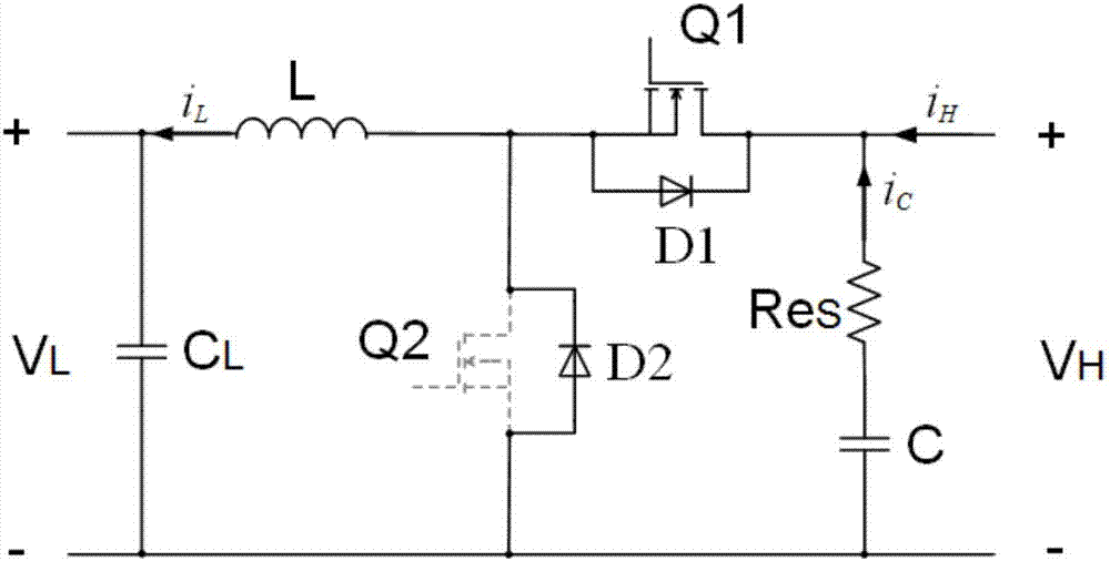
[0118] A bidirectional DC / DC power converter control circuit of this embodiment, such as figure 1 and image 3 , including voltage division detection circuit 5, A / D conversion circuit 7 and digital controller 8, also includes drive circuit 9 and voltage follower 6, bidirectional DC / DC power converter, voltage division detection circuit 5 is connected in parallel in bidirectional DC / DC The two ends of the input / output capacitor of the power converter, the voltage division detection circuit 5, the voltage follower 6, the A / D conversion circuit 7, the digital controller 8, the drive circuit 9 and the switching tube power of the bidirectional DC / DC power converter The gates of the switch tubes of circuit 3 are connected in series in sequence.
[0119] Such as figure 1 As shown, the output terminal of the voltage division detection circuit 5 is connected to the input terminal of the voltage follower 6, the output terminal of the voltage follower 6 is connected to the input termin...
Embodiment 2
[0125] A bidirectional DC / DC power converter control circuit of this embodiment, such as figure 1 , on the basis of the technical solution of embodiment 1, the described bidirectional DC / DC power converter is a non-isolated bidirectional DC / DC power converter (generally speaking, the switching tube of the non-isolated bidirectional DC / DC power converter The power circuit 3 includes two switch tubes), including an energy storage unit 1 connected in parallel, a low-voltage side filter and energy storage circuit 2, a switch tube power circuit 3 and a high-voltage side filter circuit 4, and the input / output capacitor It is the low-voltage side filter capacitor of the low-voltage side filter and energy storage circuit 2 or the high-voltage side filter circuit 4 .
[0126] The control method of the present invention is not applicable to the topology of the isolated bidirectional DC / DC power converter, because the working mode of the isolated bidirectional DC / DC power converter is co...
Embodiment 3
[0129] A bidirectional DC / DC power converter control circuit of this embodiment, such as figure 1 , further defined on the basis of the technical solution of embodiment 1 or 2, the described bidirectional DC / DC power converter is a bidirectional Buck-Boost converter, including the low-voltage side voltage V L , Low-voltage side filter capacitor C L , energy storage inductance L, switch tubes Q1 and Q2, freewheeling diode D1, freewheeling diode D2 and high-voltage side capacitor C, the energy storage unit 1 is the low-voltage side voltage V L , the low-voltage side filter and energy storage circuit 2 includes a low-voltage side filter capacitor C L and energy storage inductance L, the switching tube power circuit 3 includes switching tubes Q1 and Q2, freewheeling diode D1 and freewheeling diode D2, and the high-voltage side filter circuit 4 includes a high-voltage side capacitor C;
[0130] Low side voltage V L The positive and low side filter capacitor C L One end of and o...
PUM
 Abstract
Description
Claims
Application Information
 - R&D
- Intellectual Property
- Life Sciences
- Materials
- Tech Scout
- Unparalleled Data Quality
- Higher Quality Content
- 60% Fewer Hallucinations
Browse by: Latest US Patents, China's latest patents, Technical Efficacy Thesaurus, Application Domain, Technology Topic, Popular Technical Reports.
© 2025 PatSnap. All rights reserved.Legal|Privacy policy|Modern Slavery Act Transparency Statement|Sitemap|About US| Contact US: help@patsnap.com


