
Microstrip leaky wave antenna with metal round hole load introduced and control method thereof

A technology of leaky wave antenna and circular hole, which is applied in the direction of leaky waveguide antenna, radiation element structure, circuit, etc., can solve the problem of large size, achieve low production cost, reduce circuit layout area, and simple industrial production.

Inactive Publication Date: 2017-08-18
TIANJIN UNIV
View PDF1 Cites 0 Cited by
  • Summary
  • Abstract
  • Description
  • Claims
  • Application Information

AI Technical Summary

Problems solved by technology

Although the traditional leaky wave antenna has many advantages in performance, it has always faced the problem of oversized

Method used


Image

  • Microstrip leaky wave antenna with metal round hole load introduced and control method thereof
  • Microstrip leaky wave antenna with metal round hole load introduced and control method thereof
  • Microstrip leaky wave antenna with metal round hole load introduced and control method thereof

Examples


Embodiment Construction

[0046] The present invention will be further described below in conjunction with the accompanying drawings.

[0047] The invention protects a microstrip leaky-wave antenna that introduces a metal hole load, which is composed of a signal line layer, a dielectric layer and a metal grounding plate arranged in sequence from top to bottom. The following are the manufacturing steps and control methods of specific embodiments of the invention :

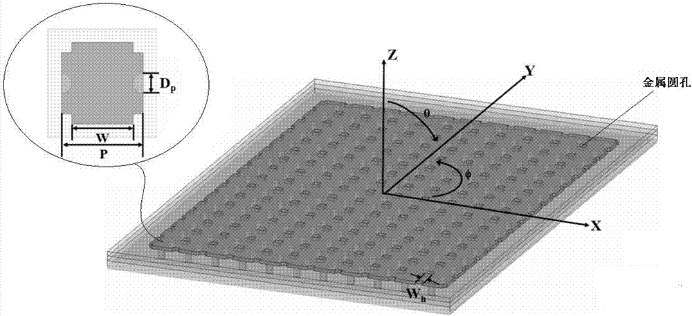
[0048] Step 1: The structure of the microstrip leaky wave antenna adopts four layers of metal and three layers of dielectric. The metal material is copper. The dielectric material parameters are: dielectric constant 4.7, loss tangent 0.008. The height of the metal layer is 16 μm, the height of the dielectric layer is h1=h2=h3=100 μm, h=h1+h2+h3=300 μm (see Picture 1-1 and 1-2 Shown), the above material parameters can be determined with the manufacturer:

[0049] Step 2: Determine the structural parameters of the designed antenna according...


PUM


Abstract

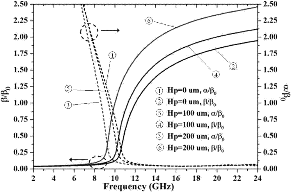
The invention discloses a microstrip leaky wave antenna with metal round hole load introduced and a control method thereof. The antenna is provided with a signal line layer, at least two dielectric layers and a metal grounding plate sequentially from top to bottom, wherein metal round holes are equidistantly arranged in the signal line layer and the dielectric layers. Starting from the problem of narrowing the length of the microstrip leaky wave antenna in a cross section direction, the metal round holes are introduced to the traditional microstrip leaky wave antenna structure, the cut-off frequency of the microstrip leaky wave antenna in a first high order EH1 mode and leakage area frequency are controlled, the two frequencies both move to a low frequency, the length of the antenna in the cross section direction can be reduced by using the feature, the circuit layout area can be reduced, and the volume of a product is reduced.

Description

technical field [0001] The invention belongs to the field of microstrip leaky-wave antennas, in particular, it relates to a microstrip leaky-wave antenna with a metal hole load and its control method, especially for the frequency of the first high-order mode EH1 modal leakage region of the microstrip antenna Control Method. Background technique [0002] Microstrip line is the most widely used planar transmission line in hybrid microwave integrated circuits and monolithic microwave integrated circuits. The microstrip antenna is on a thin dielectric substrate, one side is attached with a thin metal layer as a grounding plate, and the other side is made of a metal patch of a certain shape by photolithography, and the patch is fed by a microstrip line or a coaxial probe. Antenna made of electricity. Microstrip antennas are divided into two categories: first, when the shape of the patch is a slender strip, it is a microstrip dipole antenna; second, when the patch is an area uni...

Claims


Application Information

Patent Timeline
Patent Type & Authority Applications(China)
IPC IPC(8): H01Q13/20H01Q1/38
CPCH01Q13/20H01Q1/38
Inventor 路畅
Owner TIANJIN UNIV
Learn More