
Substrate for sensor, physical quantity detection sensor

A technology for detecting sensors and sensors, used in instruments, measuring devices, measuring acceleration, etc., can solve problems such as difficulties, inability to meet the detection range of physical quantities of acceleration, damage to sensor substrates or physical quantity detection elements, etc., to achieve the effect of thermal stress suppression

Inactive Publication Date: 2017-08-18
SEIKO EPSON CORP
View PDF9 Cites 4 Cited by
  • Summary
  • Abstract
  • Description
  • Claims
  • Application Information

AI Technical Summary

Problems solved by technology

[0006] It is known that when the outer shape of the sensor substrate is formed by wet etching a crystal in a single crystal material used as a material for forming a sensor substrate of a physical quantity detection sensor, due to the etching speed in each crystal axis direction of the crystal, Due to the etching anisotropy caused by the difference, it is difficult to form the gap in the in-plane direction between the movable part and the supporting part with the required length and with high precision.
However, in Patent Document 2, there is no description about a method of forming a gap between the movable part and the protrusion on the inner peripheral surface of the support part with high precision.
Therefore, when the gap between the movable part and the protruding part (restriction part, stopper part) is longer than a predetermined length, and the physical quantity detection sensor is given an impact exceeding the design value, there is a substrate for the sensor or a physical quantity detection sensor. Components may be damaged
In addition, in the case where the gap between the movable part and the protruding part (restricting part) is shorter than an appropriate length, since the displacement range of the movable part is restricted to be smaller than the set range, there is a possibility that the set value cannot be satisfied. It is possible to detect the range of physical quantities such as acceleration

Method used


Image

  • Substrate for sensor, physical quantity detection sensor
  • Substrate for sensor, physical quantity detection sensor
  • Substrate for sensor, physical quantity detection sensor

Examples


Embodiment

[0198] Next, an example to which the physical quantity detection sensor 100 according to one embodiment of the present invention is applied will be described with reference to the drawings.

[0199] Figure 11A It is a perspective view showing a video camera equipped with a physical quantity detection sensor 100, Figure 11B is a perspective view showing a mobile phone equipped with the physical quantity detection sensor 100, Figure 12 It is a perspective view showing an automobile as a moving body on which the physical quantity detection sensor 100 is mounted.

[0200] Electronic equipment

[0201] Such as Figure 11A , Figure 11B As shown, a video camera 500 and a mobile phone 600 as electronic devices are equipped with the physical quantity detection sensor 100 according to the present embodiment.

[0202] first, Figure 11A The shown video camera 500 includes an image receiving unit 501 , an operation unit 502 , a voice input unit 503 , and a display unit 504 . Th...


PUM


Abstract

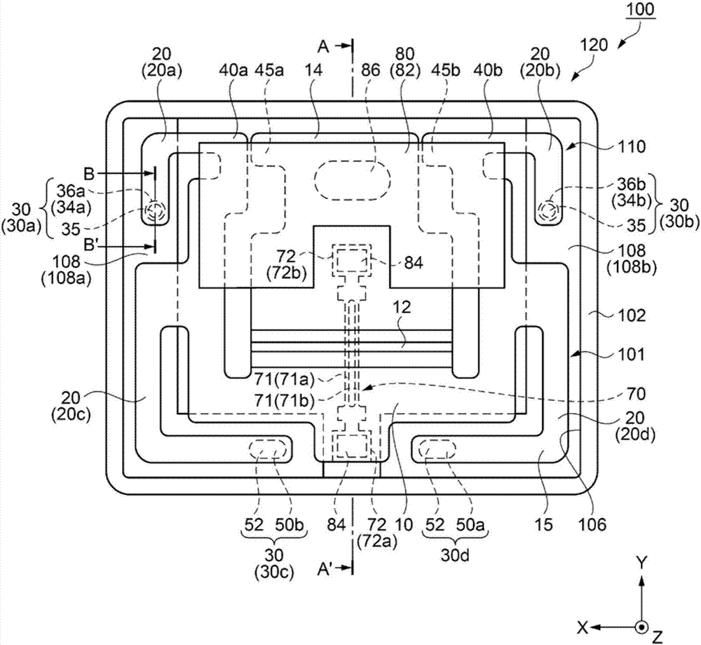
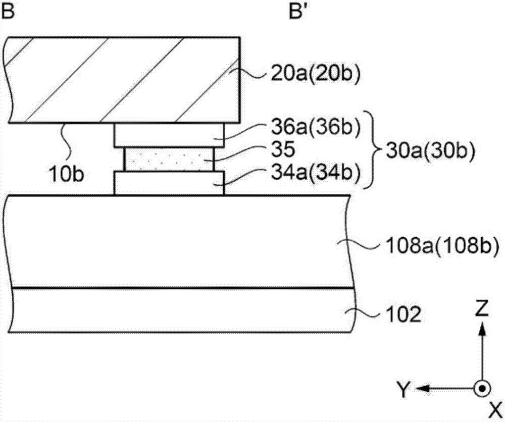
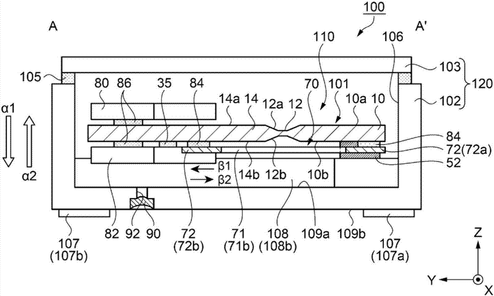
A substrate for a sensor includes: a base section; a movable section connected to the base section; an arm portion as a support portion extending along the movable section from the base section; a first gap portion having a protrusion portion in which one of the movable section and the arm portion protrudes toward the other of the movable section and the arm portion, and having a predetermined gap between the protrusion portion on one side and the other of the movable section and the support portion; and a second gap portion which is located further toward the base section side than the first gap portion has a gap wider than the predetermined gap, in which in the first gap portion, one of the movable section and the arm portion has a ridge portion on the side facing the first gap portion.

Description

technical field [0001] The present invention relates to a sensor substrate, a physical quantity detection sensor, an acceleration sensor, electronic equipment, and a moving body. Background technique [0002] Conventionally, for example, as described in Patent Document 1, there is known a physical quantity detection sensor in which a physical quantity detection element for detecting a physical quantity is fixed on a sensor substrate (cantilever portion) It has a base part (fixed part), a movable part connected to the base part, and a support part extending from the base part along the movable part in plan view viewed from the thickness direction of the movable part. In this physical quantity detection sensor, one end of the physical quantity detection element is fixed to the base part, and the other end is fixed to the movable part. In addition, the physical quantity detection sensor includes a mass portion disposed on at least one of both principal surfaces of the movable ...

Claims


Application Information

Patent Timeline
Patent Type & Authority Applications(China)
IPC IPC(8): G01P15/097
CPCG01P15/097G01P2015/0871G01P15/0907
Inventor 龟田高弘
Owner SEIKO EPSON CORP
Learn More