
Deburring device for cast steel joint

A cast steel joint and deburring technology, which is applied to machine tools, grinders, and metal processing equipment suitable for grinding workpiece edges, can solve problems such as low safety factor and low grinding efficiency, and achieve fast wear and save grinding costs , The effect of saving the use of consumables

Inactive Publication Date: 2017-08-18
SHANGHAI HONGJIN EQUIP & ENG CO LTD
View PDF6 Cites 2 Cited by
  • Summary
  • Abstract
  • Description
  • Claims
  • Application Information

AI Technical Summary

Problems solved by technology

[0005] The purpose of the present invention is to provide a deburring device for cast steel joints, thereby solving the problem of low safety factor and grinding efficiency caused by manual removal of burrs on cast steel joints in the prior art through grinders, angle grinders and other equipment. low problem

Method used


Image

  • Deburring device for cast steel joint
  • Deburring device for cast steel joint
  • Deburring device for cast steel joint

Examples


Embodiment Construction

[0027] Below, in conjunction with the accompanying drawings, preferred embodiments of the present invention are given and described in detail, so that the functions and features of the present invention can be better understood.

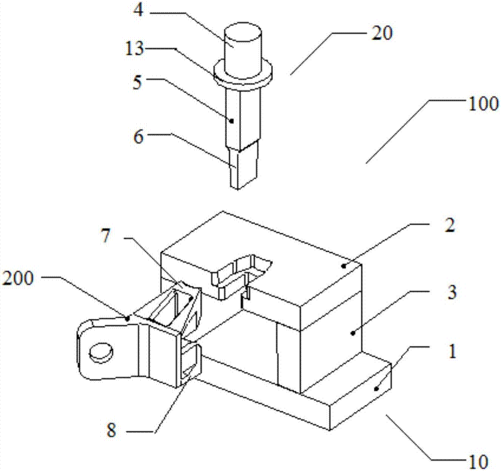
[0028] Such as figure 1 Shown is a schematic view of the state of the deburring device 100 and the cast steel joint 200 to be deburred according to a preferred embodiment of the present invention before work. The deburring device 100 mainly includes two parts: a positioning mechanism 10 and a punching mechanism 20, wherein the positioning mechanism 10 is used to fix the cast steel joint 200, and mainly includes: a base 1, a plate portion 2, a support column 3, and a punching mechanism 20 It is arranged above the positioning mechanism 10 and is used for punching the burrs on the cast steel joint 200 .

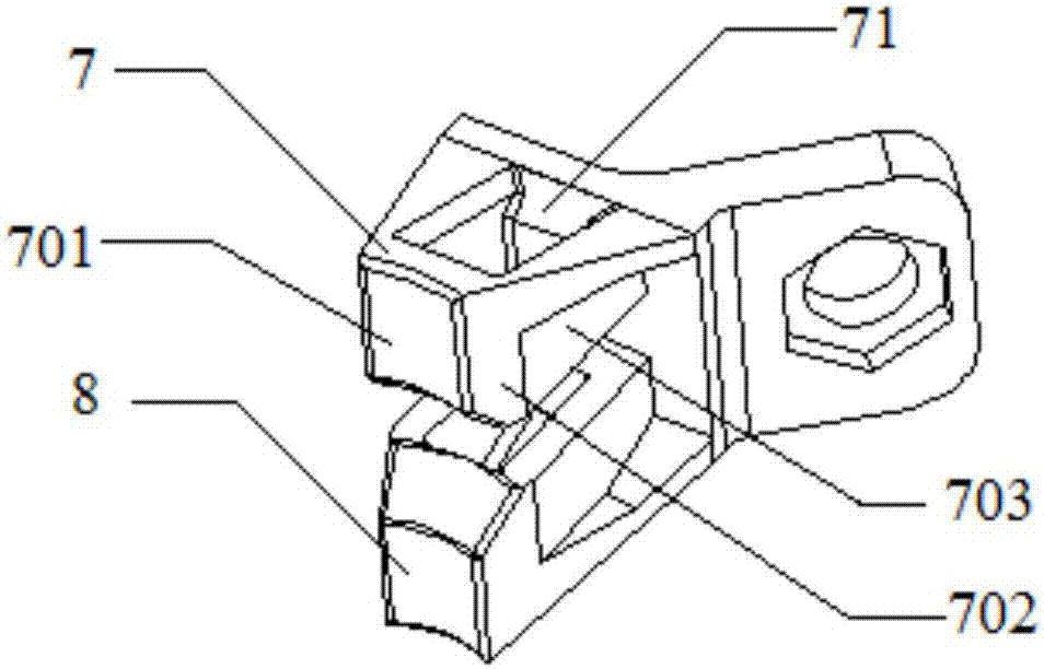
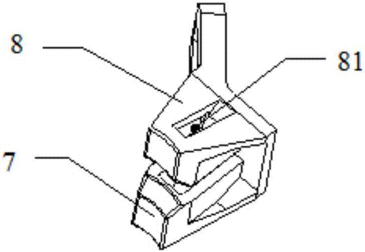
[0029] Specifically, as Figure 2A , Figure 2B As shown, the cast steel joint 200 includes a first head 7 and a second head 8 that are vertically ...


PUM


Abstract

The present invention provides a deburring device for cast steel joints, comprising: a positioning mechanism for fixing the cast steel joints, the positioning mechanism comprising: a base, and a plate extending laterally above the base, An accommodating space is kept between the board part and the base, wherein the board part has a groove inwardly recessed from one side of the board part, and the groove includes a first vertically aligned from top to bottom. A groove and a second groove, the concave size of the second groove is smaller than the concave size of the first groove so as to form a groove along the first groove between the first groove and the second groove and a punching mechanism arranged above the positioning mechanism, the punching mechanism has a cutting knife for punching burrs in the hole structure on the cast steel joint. According to the present invention, a deburring device with increased safety factor, improved grinding efficiency and reduced grinding cost is provided.

Description

technical field [0001] The present invention relates to a deburring device, more particularly to a deburring device for cast steel joints. Background technique [0002] As society continues to move forward, so does the construction industry in new directions. New technologies, new materials, and new processes are continuously developed and utilized in the construction industry, providing more fresh blood for the construction industry. In the scaffolding industry, compared with foreign advanced technologies, the domestic research and application of steel pipe support systems for building construction technology is relatively late. In the early 1950s in our country, the construction scaffolding was all made of bamboo or wood. Since the 1960s, fastener-type steel pipe scaffolding has been promoted. Since the 1980s, my country has begun to develop multi-functional scaffolding series, such as portal scaffolding series, bowl buckle steel pipe scaffolding series and so on. At t...

Claims


Application Information

Patent Timeline
Patent Type & Authority Applications(China)
IPC IPC(8): B24B9/04
CPCB24B9/04
Inventor 何子明
Owner SHANGHAI HONGJIN EQUIP & ENG CO LTD
Learn More