Organic exhaust gas treatment system and method

A technology of organic waste gas and treatment system, applied in the direction of separation method, combustion method, chemical instrument and method, etc., can solve the problems of low heat utilization rate of combustion flue gas, high equipment quality requirements, corrosion of organic waste gas, etc., and achieve reduction of combustion Burning time, avoiding secondary pollution, safe and stable burning effect

Pending Publication Date: 2017-08-18
SHANDONG UNIV
View PDF15 Cites 8 Cited by
  • Summary
  • Abstract
  • Description
  • Claims
  • Application Information

AI Technical Summary

Problems solved by technology

[0003] The traditional adsorption concentration combustion method uses the high-temperature flue gas after combustion to heat the cold air through a heat exchanger, and the temperature of the cold air rises after absorbing heat, which is used for desorption and regeneration of activated carbon; Rust, corrosion, and desorbed organic waste gas spontaneously ignites, posing safety hazards
In addition, in the combustion process, there are mainly high-temperature incineration method and catalytic combustion method; high-temperature incineration method has high requirements on the quality of equipment due to the high combustion temperature, and it is easy to generate NO at high temperature. x , prone to secondary pollution
Although the catalytic combustion method has a low combustion temperature, the equipment is complicated, and impurities often appear in the organic waste gas, and the catalyst is easily poisoned and sintered, which increases the operating cost
In addition, the combustion method will produce a large amount of CO 2 gas, which also contributes to the greenhouse effect
[0004] To sum up, the organic waste gas treatment methods in the prior art have problems such as high equipment requirements, easy to produce secondary pollution, and low heat utilization rate of combustion flue gas, and there is still no effective solution

Method used


Image

  • Organic exhaust gas treatment system and method

Examples


Embodiment Construction

[0046] It should be pointed out that the following detailed description is exemplary and intended to provide further explanation to the present application. Unless defined otherwise, all technical and scientific terms used herein have the same meaning as commonly understood by one of ordinary skill in the art to which this application belongs.

[0047] It should be noted that the terminology used here is only for describing specific implementations, and is not intended to limit the exemplary implementations according to the present application. As used herein, unless the context clearly dictates otherwise, the singular is intended to include the plural, and it should also be understood that when the terms "comprising" and / or "comprising" are used in this specification, they mean There are features, steps, operations, means, components and / or combinations thereof.

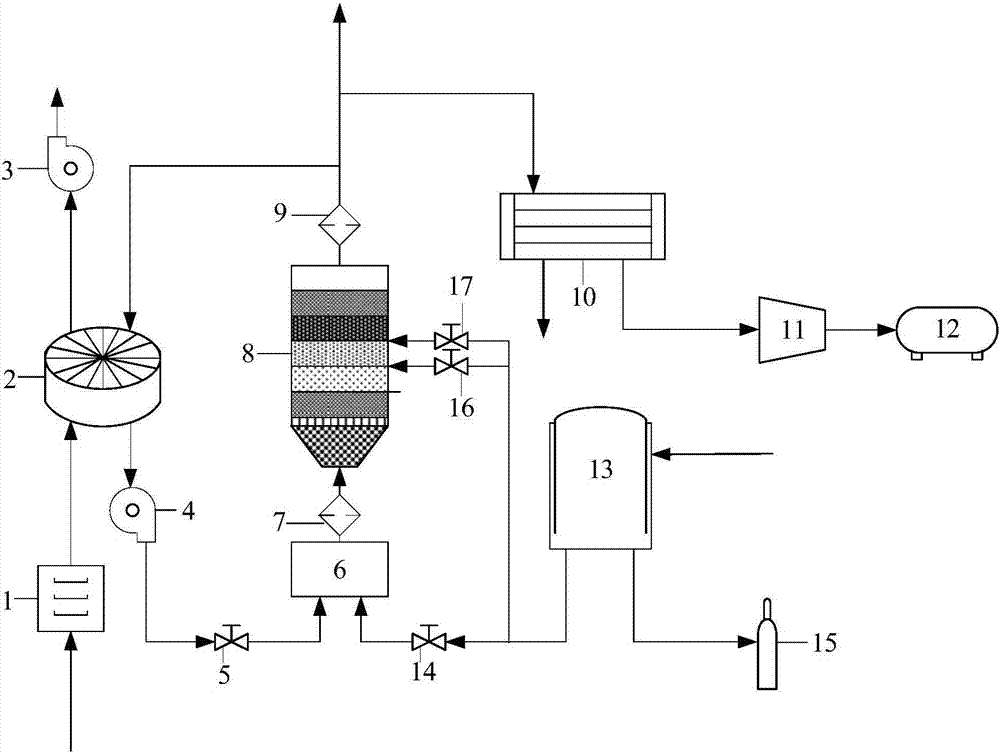
[0048] Such as figure 1 As shown, an organic waste gas treatment system and treatment method, the treatment met...


PUM

PropertyMeasurementUnit
Apertureaaaaaaaaaa

Abstract

The invention discloses an organic exhaust gas treatment system and method. The organic exhaust gas treatment system comprises a dust remover, an adsorber, a combustor and an oxygen source, wherein an inlet of the dust remover is connected with an organic exhaust gas source, an outlet of the dust remover is connected with an adsorption inlet of the adsorber, a desorption outlet of the adsorber is connected with an inlet of the combustor, an outlet of the combustor is connected with a desorption inlet of the adsorber, and the oxygen source is connected with an inlet of the combustor. The combustor is sequentially provided with a mixing chamber, a gas distributor and a uniform combustion chamber from bottom to top. The mixing chamber is provided with an organic exhaust gas pipeline and an oxygen pipeline. The combustion chamber is filled with a nonuniform honeycomb structure, the honeycomb structure comprises an upper layer, a middle layer and an upper layer, the middle layer is a combustion zone, the lower layer and the upper layer are smaller than the middle layer in hole diameter, and the hole diameter and porosity of the middle layer are progressively increased from bottom to top. The problems of high device requirement, easily produced secondary pollution, low combustion smoke heat utilization rate and the like of an organic exhaust gas treatment method in the prior art can be solved.

Description

technical field [0001] The invention belongs to the field of organic waste gas pollution control, and in particular relates to an organic waste gas treatment system and treatment method. Background technique [0002] At present, the methods for treating industrial organic waste gas at home and abroad mainly include adsorption method, combustion method and biological purification method; the adsorption method is suitable for the treatment of organic waste gas with large discharge volume and low concentration, and the combustion method is suitable for the treatment of organic waste gas with high concentration and no recovery value , The biological purification method is suitable for the treatment of low-concentration and toxic organic waste gas. In the actual industrial organic waste gas treatment, it is necessary to use a combination of various technologies to improve the efficiency of waste gas treatment according to the characteristics of different organic waste gases. For...

Claims


Application Information

Patent Timeline
IPC IPC(8): B01D46/02B01D53/06F23G7/06
CPCB01D46/023B01D53/06F23G7/06F23G2207/20F23G2207/30F23G2206/20
Inventor 王志强户英杰程星星马春元
Owner SHANDONG UNIV
Why Eureka
Try Eureka