
Current ring starting method for permanent magnet synchronous motor with variable PID parameters

A permanent magnet synchronous motor, current loop technology, applied in the control of generators, motor generator control, control of electromechanical brakes and other directions, can solve the problems of starting out of step, non-adjustable PID controller parameters, overcurrent and other problems

Active Publication Date: 2017-08-15
SOUTHEAST UNIV
View PDF4 Cites 17 Cited by
  • Summary
  • Abstract
  • Description
  • Claims
  • Application Information

AI Technical Summary

Problems solved by technology

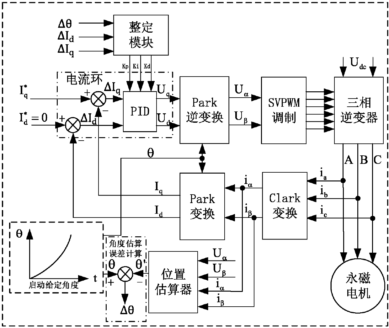
[0009] Purpose of the invention: In order to solve the technical problems that the parameters of the PID controller cannot be adjusted in the current loop control of the above-mentioned traditional permanent magnet synchronous motor, and the technical problems of overcurrent and out-of-step are prone to occur, the present invention proposes a variable PID parameter current loop of the permanent magnet synchronous motor start method

Method used


Image

  • Current ring starting method for permanent magnet synchronous motor with variable PID parameters
  • Current ring starting method for permanent magnet synchronous motor with variable PID parameters
  • Current ring starting method for permanent magnet synchronous motor with variable PID parameters

Examples


Embodiment Construction

[0068] The present invention aims at the deficiencies existing in the current permanent magnet synchronous motor control scheme, and proposes a variable PID parameter current loop starting method for the permanent magnet synchronous motor. , The problem of starting out of step improves the reliability of the permanent magnet synchronous motor without position control and improves the control performance.

[0069] The technical solution proposed by the present invention will be described in detail below with reference to the accompanying drawings.

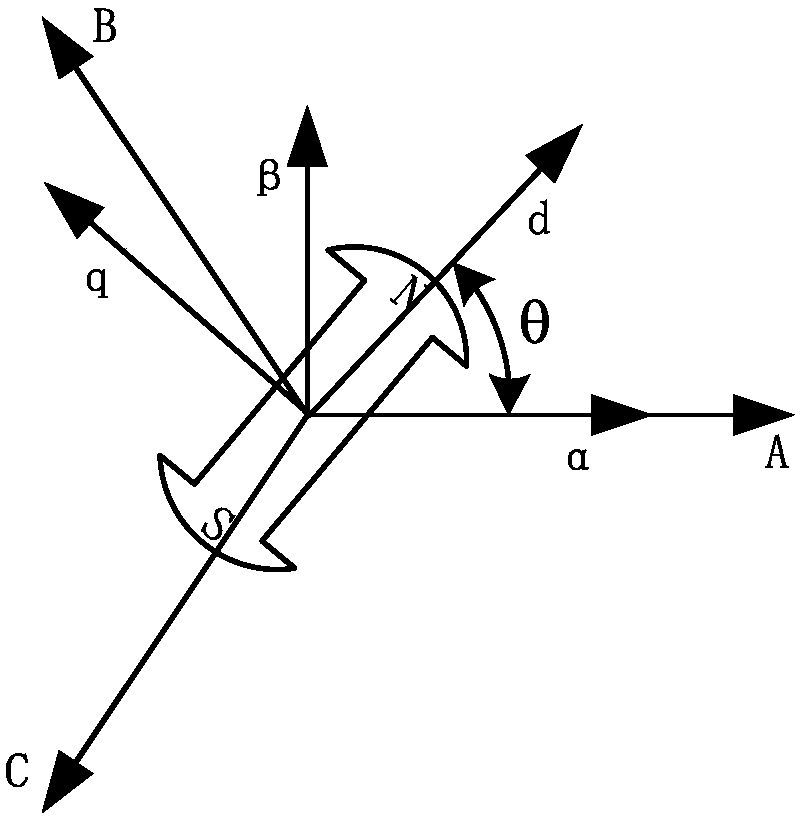
[0070] figure 2 It is the relationship diagram of the space coordinate system of the control algorithm of the present invention.

[0071] N-S is the permanent magnet of the permanent magnet synchronous motor. The permanent magnet rotor will generate a constant magnetic field in space. When the three-phase symmetrical sine wave alternating current is passed into the three-phase stator windings A, B, and C, a spatial rotating magnet...


PUM


Abstract

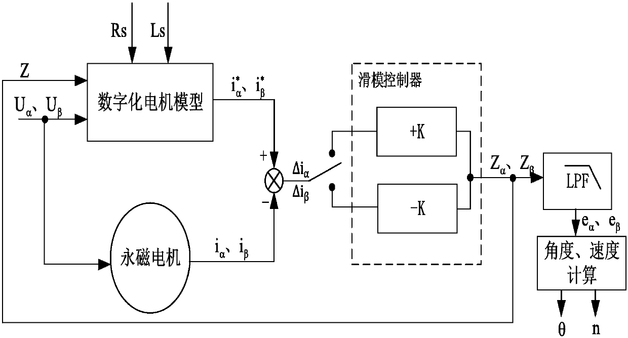
The invention provides a current ring starting method for a permanent magnet synchronous motor with variable PID parameters. The current ring starting method comprises the steps as follows: a three-phase winding of the motor is powered on to enable the N pole of a rotor to be stopped in the position of an A-axis direction of an ABC coordinate system, wherein the rotor position angle <theta> is equal to 0 at the moment; a three-phase symmetrical sine alternating voltage is pumped to the three-phase winding of the motor, the voltage frequency f is constantly increased, and the motor starts acceleration; the set rotor position angle <theta> is increased progressively; after the motor is started, a position estimator begins to estimate a rotor position <theta>', and an error value <delta> <theta> between the <theta>' and <theta> is calculated; the parameters of Kp, Ki and Kd of the current ring are adjusted through a setting module according to the estimation error <delta> <theta>, a motor stator excitation component current error value <delta>Id and a torque component current error value <delta>Iq, and after configuration is completed, the current ring is executed. By virtue of the current ring starting method, the no-position start of the permanent magnet synchronous motor can be more reliable and safer; and in addition, the control cost is low, and the control system is high in dynamic performance and high in anti-interference capability.

Description

technical field [0001] The invention relates to the field of starting a permanent magnet synchronous motor, in particular to a method for starting a permanent magnet synchronous motor with a variable PID parameter current loop. Background technique [0002] The permanent magnet synchronous motor adopts electronic commutation, which can avoid the noise and loss caused by the traditional mechanical transmission device, can improve the operating efficiency of the system, reduce vibration noise, and has many incomparable advantages compared with other motors. [0003] In the control of permanent magnet synchronous motors, it is necessary to determine the position and speed information of the rotor. Traditionally, the installation of position sensors must affect the structure of the motor, which usually increases the cost and complexity of the system. The use of non-position control can reduce the cost of control. Improve the running stability and reliability of the motor. [00...

Claims


Application Information

Patent Timeline
IPC IPC(8): H02P21/18H02P21/22H02P25/03H02P27/08
CPCH02P21/0003H02P25/03H02P27/08
Inventor 黄允凯许欢夏天琦徐菲菲祝子冲
Owner SOUTHEAST UNIV
Learn More