FRP pipe concrete thin-wall box-shaped section component

A concrete and FRP board technology, applied in arched beams, truss structures, joists, etc., can solve the problems of stress concentration at corners, residual stress, affecting the corrosion resistance of thin-walled box sections, etc., and achieve fast construction speed. , The effect of reducing self-weight and reusable construction speed

Inactive Publication Date: 2017-08-15
NANJING INST OF TECH
View PDF5 Cites 0 Cited by
  • Summary
  • Abstract
  • Description
  • Claims
  • Application Information

AI Technical Summary

Problems solved by technology

[0003] The object of the present invention is to provide a fiber composite material (FRP) tubular concrete thin-walled box-section member to solve the problems affecting the corrosion resistance of the thin-walled box-section and the problems of stress concentration and residual stress existing at corners

Method used


Image

  • FRP pipe concrete thin-wall box-shaped section component
  • FRP pipe concrete thin-wall box-shaped section component
  • FRP pipe concrete thin-wall box-shaped section component

Examples


Embodiment 1

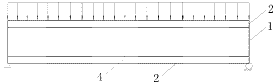
[0035] combine figure 1 , figure 2 As shown, the prestressed FRP tube concrete member of this embodiment is a closed box section, the FRP tube is located at the corner of the section, and the FRP tube 2 and the thin-walled FRP plate 1 are bonded by epoxy resin. The FRP pipe 2 located on the axial compression side of the entire section is filled with concrete 3 to form an FRP pipe-concrete composite part 4 to bear the compressive stress caused by the bending moment; the FRP pipe 2 located on the axial tension side of the entire section is not Filling with concrete can effectively reduce the weight and cost of the entire component. The cross-section of the components in this embodiment is generally rectangular, and can also be designed as other polygonal cross-sections such as squares, triangles, and trapezoids. The components can be disassembled into several parts for factory prefabrication, and assembled on site by welding (epoxy resin bonding).

[0036] The FRP pipe is pre...

Embodiment 2

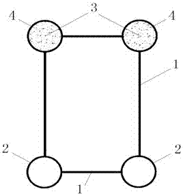
[0039] combine image 3 , Figure 4 , The difference between the structure of this embodiment and Example 1 is that all FRP pipes 2 are filled with concrete 3 to form an FRP pipe-concrete composite part 4 . The figure is a box-shaped cross-section member, and it can also be designed as a cross-sectional form of other polygonal shapes such as a square, a triangle, and a trapezoid. Other components are the same as in Embodiment 1.

Embodiment 3

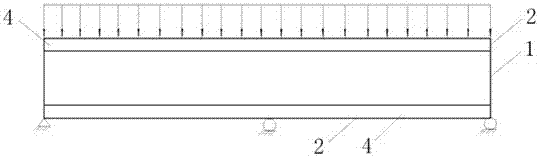
[0041] combine Figure 5 , Figure 6 As shown, this implementation part is an FRP tube concrete thin-walled box-section member bearing axial pressure, FRP tube 2 is filled with concrete 3 to form an FRP tube-concrete composite part 4, and the box section is filled with concrete 3 to form FRP tube concrete 5 . The figure is a box-shaped cross-section member, which can also be designed as a square, triangle, trapezoid and other polygonal cross-section forms. Other components are the same as in Embodiment 1.


PUM

PropertyMeasurementUnit
Thicknessaaaaaaaaaa

Abstract

The invention relates to an FRP pipe concrete thin-wall box-shaped section component and belongs to a steel pipe concrete component. The FRP pipe concrete thin-wall box-shaped section component comprises FRP pipes, thin-wall FRP plates and concrete. The FRP pipes and the thin-wall FRP plates form a thin-wall box-shaped section, the FRP pipes are located at the corners of the thin-wall box-shaped section, the enclosed spaces formed through division of the FRP pipes and the thin-wall box-shaped section are filled with the concrete to form FRP pipe-concrete combined parts and a steel pipe concrete part, and the FRP pipes and thin-wall steel plates are adhered together through epoxy resin. According to the component, the FRP pipes are arranged at the corners of the whole section, the problem that serious residual stress exists at the corners of square steel pipes in square steel pipe concrete is effectively solved, and anti-corrosion performance of the kind of components can be further improved. The FRP pipes are filled with the concrete to form the FRP pipe-concrete combined parts, and thus the combined effect between the concrete and the FRP pipes can be given into full play.

Description

technical field [0001] The invention relates to an FRP tube concrete component, in particular to an FRP tube concrete thin-walled box-shaped section component. Background technique [0002] At present, the concrete-filled steel pipe members in the housing construction in our country mainly use steel round pipes or square steel pipes filled with concrete as structural load-bearing members. Concrete-filled steel tube members can be used not only as flexural members, axial compression members, but also as compression-bending (tension-bending) members in various parts of building structures. At present, one of the main problems encountered in the actual engineering application of steel pipe concrete members is that the exposed steel pipes need to be treated with anticorrosion, and they cannot be used in corrosive environments such as oceans; another problem is that when square steel pipes are used, the four corners of the square steel pipes are welded or cold-formed. Forming, t...

Claims


Application Information

Patent Timeline
IPC IPC(8): E04C3/29E04C3/36E04C3/46
CPCE04C3/29E04C3/36E04C3/46
Inventor 张文福过轶青耿方方肖同亮臧华赵文艳
Owner NANJING INST OF TECH
Why Eureka
Try Eureka