Spiral groove forming die

A technology of spiral groove and forming die, which is applied in the field of metal stamping processing, can solve the problems of inability to integrate into stamping processing, high investment cost of manipulators, and low profit margin, etc., to achieve the effects of ensuring coaxiality, avoiding shape distortion, and improving processing efficiency

Active Publication Date: 2019-03-19
苏州铭峰精密机械有限公司
View PDF8 Cites 0 Cited by
  • Summary
  • Abstract
  • Description
  • Claims
  • Application Information

AI Technical Summary

Problems solved by technology

Processing snap ring 31 structure abroad is usually completed by manipulators, but manipulators have high input costs and cannot be integrated into stamping processing, resulting in low production efficiency
Adoption of this approach results in low profit margins and weak competitiveness for the business

Method used


Image

  • Spiral groove forming die
  • Spiral groove forming die
  • Spiral groove forming die

Examples


Embodiment Construction

[0041] The present invention will be described in further detail below in conjunction with specific embodiments.

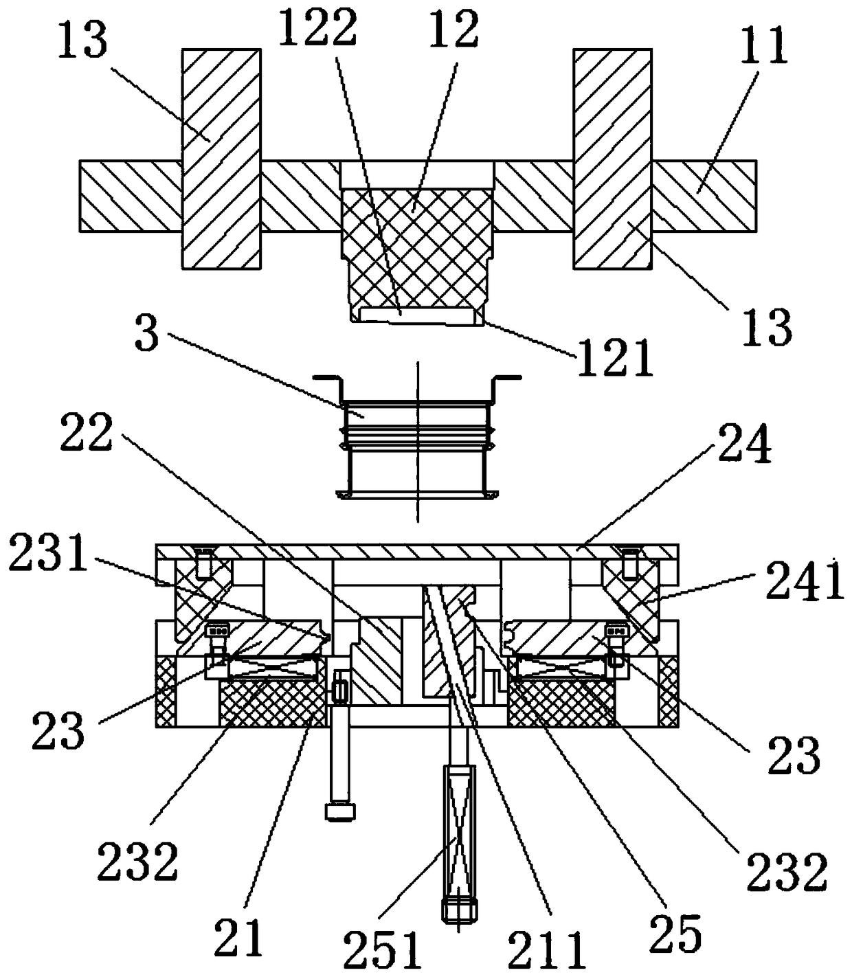
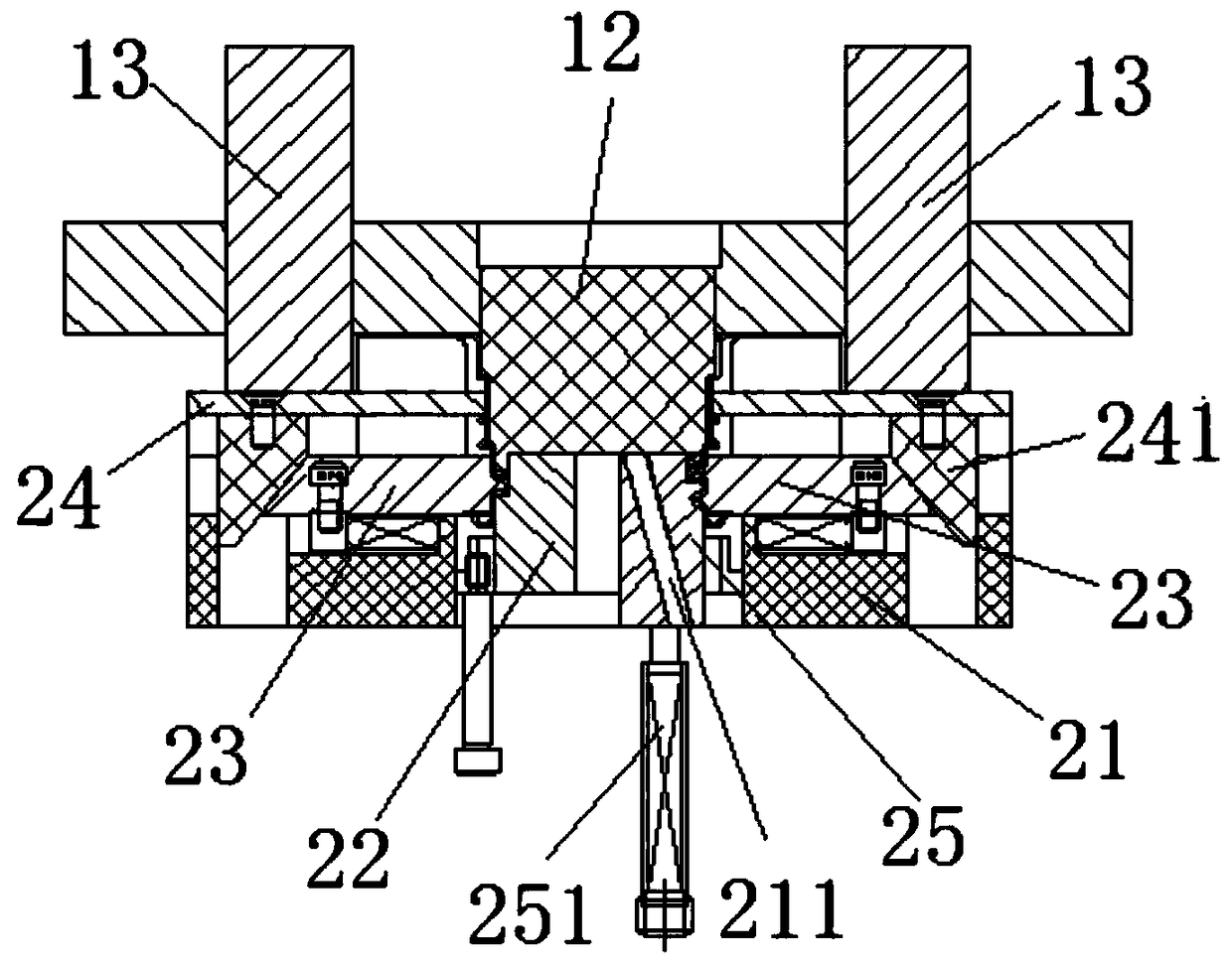
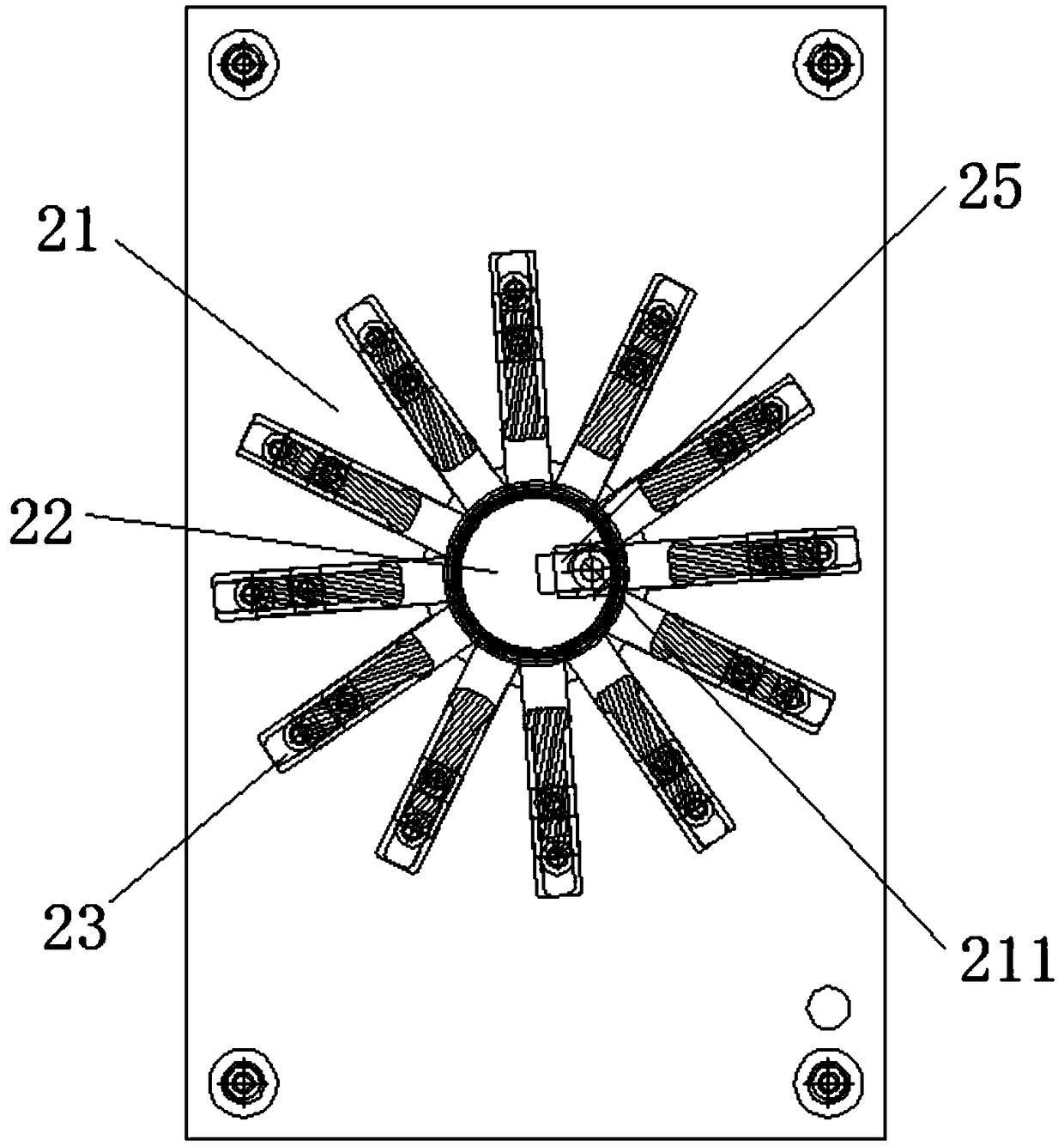
[0042] Such as Figure 1 to Figure 4 As shown, a spiral groove molding die of the present invention includes an upper template 11 and a lower template 21 arranged oppositely, and the upper template 11 is provided with a forming punch 12 located in the middle; the lower template 21 is provided with a corresponding forming punch 12 The molding block 22 and several forming sliders 23 that can move radially along the forming block 22 around the forming block 22, the forming punch 12 and the forming block 22 can be combined to form a thread forming groove (not marked) , The forming slider 23 has a forming ridge 231 that can be pressed into the thread forming groove. During processing, the fuel tank filling port 3 material without a spiral groove is set on the forming bracket 22, and in the mold closing process, the forming punch 12 is spliced ​​with the forming bracke...


PUM


Abstract

The invention belongs to the technical field of metal stamping and relates to a spiral groove forming die and a fuel tank fuel filling opening with a spiral groove. The die comprises an upper die plate and a lower die plate which are oppositely arranged. A forming punch located in the middle is arranged on the upper die plate. A forming support block corresponding to the forming punch and multiple forming sliding blocks which are arranged around the forming support block and can move along the forming support block in the radial direction are arranged on the lower die plate. The forming punch and the forming support block can be spliced into a thread forming groove. Each forming sliding block is provided with a forming protruding rib capable of being pressed into the thread forming groove. By the adoption of the forming die, the spiral groove can be machined through the thread forming groove and the forming sliding blocks, the spiral groove forming process can be fused into continuous die machining, the machining efficiency is improved, and the cost is lowered as well.

Description

technical field [0001] The invention relates to the technical field of metal stamping processing, in particular to a spiral groove forming die with low cost and fast processing. Background technique [0002] With the continuous development of stamping technology in our country and the increasing pressure of competition in the automobile market, many parts imported from abroad will be localized. [0003] Figure 4 Shown is a fuel tank 3 with a protruding snap ring 31 on it, and the snap ring 31 structure is usually processed and formed on the basis of the stretched part after stretching out the overall sleeve shape. Processing the structure of snap ring 31 abroad is usually done by manipulators. However, manipulators have high input costs and cannot be integrated into stamping processing, resulting in low production efficiency. Adopting this method leads to low profit margins and weak competitiveness of enterprises. [0004] Therefore, it is necessary to provide a new mold...

Claims


Application Information

Patent Timeline
Patent Type & Authority Patents(China)
IPC IPC(8): B21D37/10B21D51/40
CPCB21D37/10B21D51/40
Inventor 顾大明
Owner 苏州铭峰精密机械有限公司
Why Eureka
Try Eureka