
Free bending forming method for spiral three-dimensional complex bent piece

A bending forming and spiral technology, which is applied in the field of free bending forming of spiral three-dimensional complex curved parts, can solve the problems of difficult control of bending radius and pitch, large equipment investment, and increased manufacturing cost, and achieve important engineering application value, Obvious economic benefit, simple and feasible method

Active Publication Date: 2017-08-04
NANJING UNIV OF AERONAUTICS & ASTRONAUTICS +1
View PDF6 Cites 9 Cited by
  • Summary
  • Abstract
  • Description
  • Claims
  • Application Information

AI Technical Summary

Problems solved by technology

However, these traditional methods have their own shortcomings: the section distortion and wall thickness of the pipe after bending vary greatly, and the spiral three-dimensional complex bending parts with different curvature radii and pipe diameters must be replaced with different molds, which increases the manufacturing cost; There is a certain limit to the bending radius of the bend, which is only suitable for thick-walled pipes that require a large curvature radius, and the bending radius and pitch are extremely difficult to control; the intermediate frequency induction unit in the intermediate frequency bending pipe consumes a lot of power and equipment investment is large; the flame Due to the low flame heating efficiency, the pipe bending machine is only suitable for bending thin-walled spiral three-dimensional complex bending parts
However, for spiral three-dimensional complex bending parts, the domestic three-dimensional free bending system does not yet have a complete set of forming process analysis methods

Method used

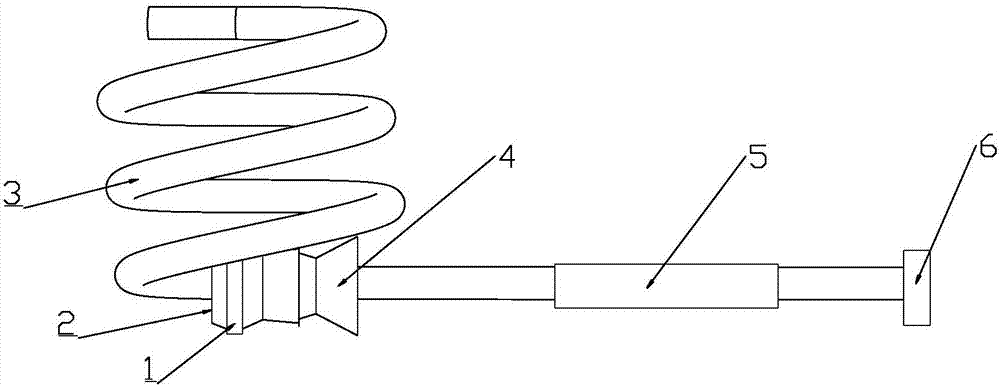
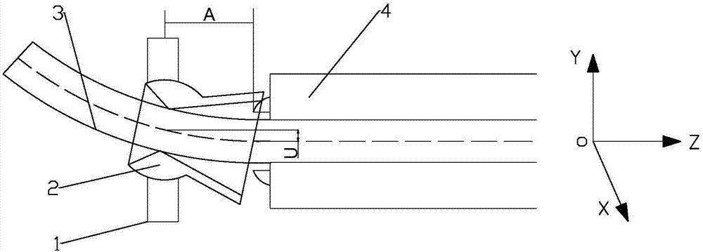

Image

  • Free bending forming method for spiral three-dimensional complex bent piece
  • Free bending forming method for spiral three-dimensional complex bent piece
  • Free bending forming method for spiral three-dimensional complex bent piece

Examples


Embodiment 1

[0047] Figure 4 It is a spiral three-dimensional complex curved part with a cylindrical diameter of 120mm, a pitch of 30mm, a number of spiral turns of 2, and a pipe outer diameter of 15mm. The specific forming process steps are as follows:

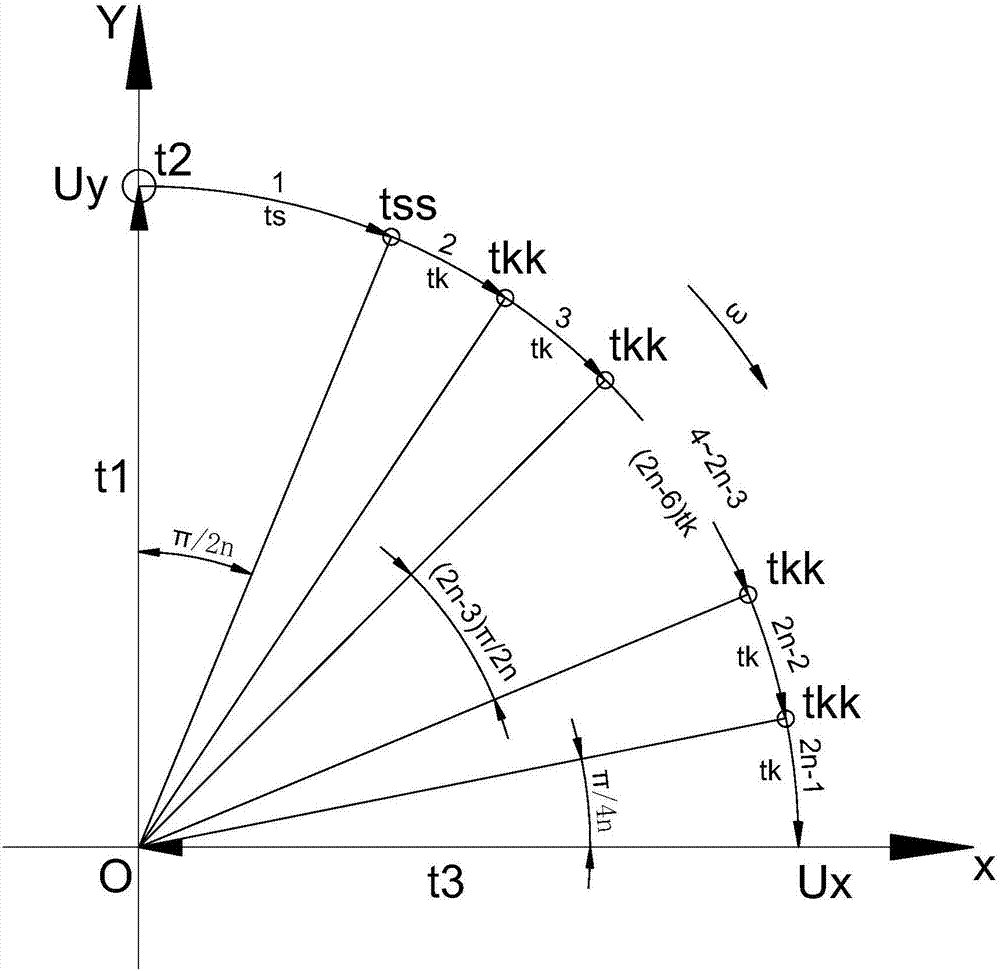
[0048] First, determine the bending radius R=D / 2=60mm according to the diameter of the cylinder D=120mm, and determine according to the bending radius 60mm, the moving speed of the pipe in the Z direction v=20mm / s and the distance A=30mm between the center of the bending die and the front end of the guiding mechanism Y-direction eccentricity Uy, movement time t1 and residence time t2;

[0049]

[0050]

[0051]

[0052]

[0053] Second, according to the number of spiral turns n=2, determine the number of deflection N of the bending die and the angle θn of each deflection during the movement of the bending die from the Uy position to the Ux position;

[0054] N=2n-1=2×2-1=3

[0055]

[0056] Third, calculate the single-tu...

Embodiment 2

[0066] Figure 5 It is a helical three-dimensional complex curved part with a cylindrical diameter of 150 mm, a pitch of 15 mm, a number of helical turns of 5, and a pipe outer diameter of 6 mm. The specific forming process steps are as follows:

[0067] First, determine the bending radius R=D / 2=75mm according to the diameter of the cylinder D=150mm, and determine according to the bending radius 75mm, the moving speed of the pipe in the Z direction v=20mm / s and the distance A=30mm between the center of the bending die and the front end of the guiding mechanism Y-direction eccentricity Uy, movement time t1 and residence time t2;

[0068]

[0069]

[0070]

[0071] Second, according to the number of spiral turns n=3, determine the number of deflection N of the bending die and the angle θn of each deflection during the movement of the bending die from the Uy position to the Ux position;

[0072] N=2n-1=2×3-1=5

[0073]

[0074] Third, calculate the single-turn spira...

Embodiment 3

[0084] Figure 6 It is a helical three-dimensional complex curved part with a cylindrical diameter of 200mm, a pitch of 10mm, a number of helical turns of 10, and a pipe outer diameter of 4mm. The specific forming process steps are as follows:

[0085] First, determine the bending radius R=D / 2=100mm according to the diameter of the cylinder D=200mm, and determine according to the bending radius 100mm, the moving speed of the pipe in the Z direction v=20mm / s and the distance A=30mm between the center of the bending die and the front end of the guiding mechanism Y-direction eccentricity Uy, movement time t1 and residence time t2;

[0086]

[0087]

[0088]

[0089] Second, determine the deflection times N of the bending die and the angle θn of each deflection during the movement of the bending die from the Uy position to the Ux position according to the number of spiral turns n=10;

[0090] N=2n-1=2×10-1=19

[0091]

[0092] Third, calculate the length L of the sin...


PUM


Abstract

The invention discloses a free bending forming method for a spiral three-dimensional complex bent piece. A pipe is fed at the constant speed in the Z direction, a bending die starts to move to the Y-direction eccentric distance Uy position with the assigned bending radius R within the time of t1 from the initial position O, and the bending die stays at the position for the time of t2 so that a half arc length can be formed; then, the bending die starts from the Uy position in the XY plane with O as the circle center and the eccentric distance Uy as the radius to form the 1 / 4 arc track, the bending die finally moves to the X-direction eccentric distance Ux position through several times of deflection and staying and then does not stay, and the bending die returns to the initial position O within the time of t3. The method is a matched bending technology analysis scheme for the pipe three-dimensional free bending device, and the beneficial effects that the pipe three-dimensional free bending device can achieve complex modeling metal component bending and one-time flexible forming are brought into full play; and the method is simple and feasible, the production efficiency is high, and important engineering application value and obvious economic benefits are achieved in the fields of aerospace, nuclear power, automobiles and other projects.

Description

technical field [0001] The invention belongs to the technical field of flexible manufacturing of metal complex components, in particular to a free bending forming method of a spiral three-dimensional complex bending part. Background technique [0002] The spiral three-dimensional complex bending part is an important part of the bending pipe. For example, the spiral coil pipe, which is a special product of the ring part, has the advantages of large heat transfer area and high heat transfer efficiency. It has been widely used in petroleum, chemical industry, metallurgy, Construction, shipbuilding, urban central heating, air conditioning, hot water supply systems, distillation condensers and solvent coolers for washing machines, etc. At present, the production methods of spiral three-dimensional complex bending parts are generally processed and manufactured by forming processes such as winding, rolling, intermediate frequency induction heating bending and flame heating bending....

Claims


Application Information

Patent Timeline
IPC IPC(8): B21D11/06B21F3/02
CPCB21D11/06B21F3/02
Inventor 靳凯郭训忠徐勇熊昊马燕楠陈文亮陶杰张士宏
Owner NANJING UNIV OF AERONAUTICS & ASTRONAUTICS
Learn More