
Manufacturing method of retardation film

A manufacturing method and technology of retardation film, applied to flat products, polarizing elements, household appliances, etc., can solve the problems of large size change and uneven degree of size change of the retardation film, and achieve less size change and size change Uniformity and high efficiency

Active Publication Date: 2020-03-13
NITTO DENKO CORP
View PDF4 Cites 0 Cited by
  • Summary
  • Abstract
  • Description
  • Claims
  • Application Information

AI Technical Summary

Problems solved by technology

However, the techniques proposed so far all have the following problems: the obtained retardation film has a large dimensional change (especially a dimensional change during heating), and in addition, the degree of dimensional change in the width direction of the film is not uniform.

Method used


Image

  • Manufacturing method of retardation film
  • Manufacturing method of retardation film
  • Manufacturing method of retardation film

Examples


Embodiment 1

[0089] (Production of polycarbonate resin film)

[0090] Polymerization was performed using a batch polymerization apparatus composed of two vertical reactors equipped with stirring blades and a reflux cooler controlled to 100°C. 9,9-[4-(2-hydroxyethoxy)phenyl]fluorene (BHEPF), isosorbide (ISB), diethylene glycol (DEG), diphenyl carbonate (DPC), and acetic acid Magnesium tetrahydrate becomes BHEPF / ISB / DEG / DPC / magnesium acetate=0.348 / 0.490 / 0.162 / 1.005 / 1.00×10 in molar ratio -5 way was added. After the inside of the reactor was sufficiently replaced with nitrogen (oxygen concentration: 0.0005 to 0.001 vol%), heating was performed with a heat medium, and stirring was started when the internal temperature reached 100°C. 40 minutes after the start of the temperature rise, the internal temperature was brought to 220° C., and the pressure was reduced while controlling to maintain the temperature, and the pressure was 13.3 kPa 90 minutes after reaching 220° C. The phenol vapor that...

Embodiment 2

[0099] A retardation film was obtained in the same manner as in Example 1, except that a cycloolefin-based resin film (“ZEONORZF-14 film” manufactured by Zeon Corporation, thickness 100 μm, width 765 mm) was used instead of the polycarbonate-based resin film. . The evaluation similar to Example 1 was performed about the obtained retardation film. The results are shown in Table 1.

Embodiment 3

[0101] (Production of polyvinyl acetal resin film)

[0102] After drying 880 g of polyvinyl alcohol-based resin [manufactured by Nippon Synthetic Chemical Co., Ltd., trade name "NH-18" (polymerization degree = 1800, saponification degree = 99.0%)] at 105 ° C for 2 hours, it was dissolved in 16.72 kg of dimethylsulfoxide (DMSO). Here, 298 g of 2-methoxy-1-naphthaldehyde and 80 g of p-toluenesulfonic acid monohydrate were added, and stirred at 40° C. for 1 hour. After adding 318 g of benzaldehyde to the reaction solution and stirring at 40° C. for 1 hour, 457 g of dimethyl acetal was also added and stirred at 40° C. for 3 hours. Then, 213 g of triethylamine was added to terminate the reaction. The obtained crude product was reprecipitated with methanol. The filtered polymer was dissolved in tetrahydrofuran, and reprecipitated with methanol again. This was filtered and dried to obtain 1.19 kg of a white polymer.

[0103] The resulting polymer was 1 H-NMR (nuclear magnetic r...


PUM

PropertyMeasurementUnit
glass transition temperatureaaaaaaaaaa

Abstract

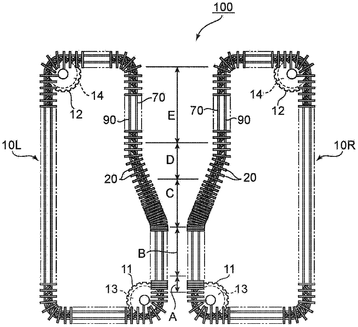
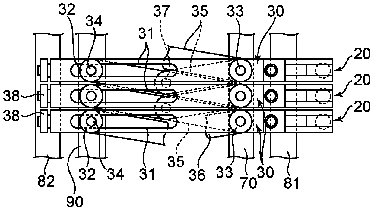
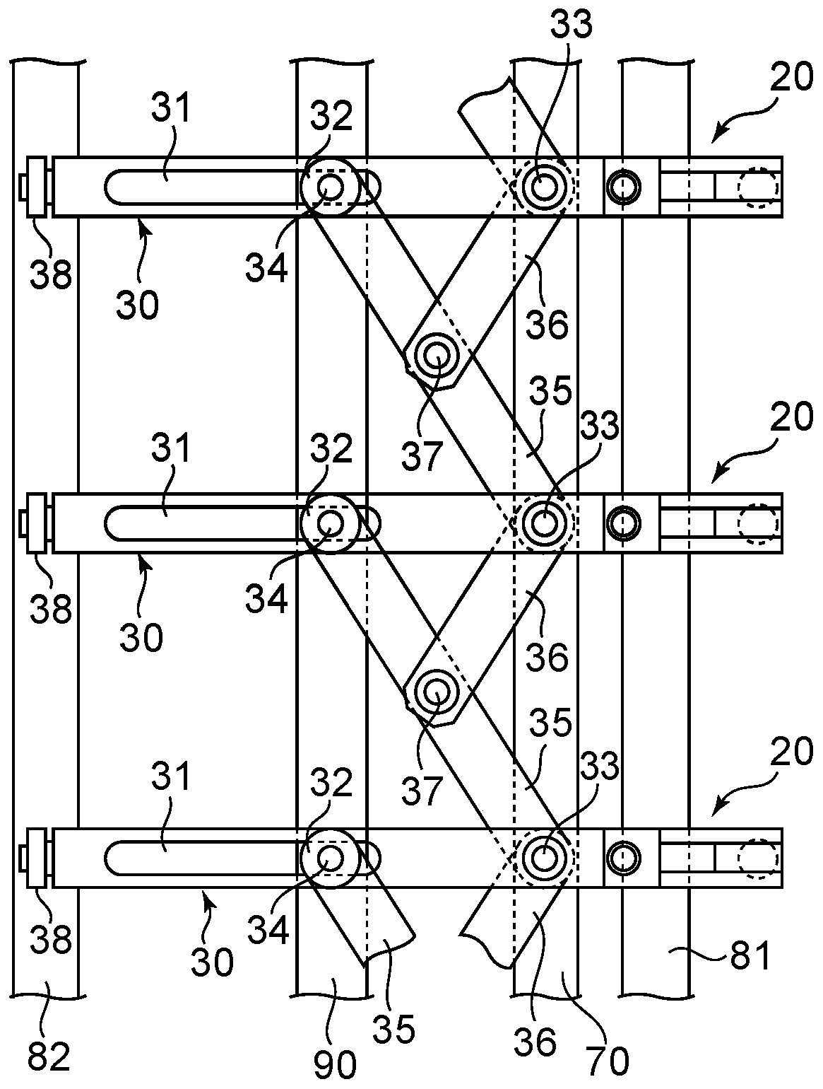
Provided is a method capable of manufacturing with high manufacturing efficiency a phase difference film with few dimensional changes and with uniform degree of dimensional changes within the film in the case where slight dimensional changes do occur. The manufacturing method for the phase difference film according to the present invention comprises: gripping the left and right ends of the film with variable pitch-type left-right clips for which the clip pitch is variable; preheating the film; changing the clip pitch of the left-right clips independently to diagonally stretch the film; reducing the clip pitch of the left-right clips to contract the film; and releasing the clip gripping the film; wherein the contracting step comprises reducing the clip pitch of the respective clips to a predetermined pitch in a state setting a position where the clip pitch of one of the clips begins to decline and a position where the clip pitch of the other clip begins to decline as different positions in the vertical direction.

Description

technical field [0001] The present invention relates to a manufacturing method of a retardation film. Background technique [0002] In image display devices such as liquid crystal display devices (LCD) and organic electroluminescent display devices (OLED), circularly polarizing plates are used for the purpose of improving display characteristics and antireflection. A circular polarizing plate is typically configured by laminating a polarizing plate and a retardation film (typically a λ / 4 plate) such that the absorption axis of the polarizing plate forms an angle of 45° with the slow axis of the retardation film. In the past, retardation films were typically produced by uniaxial or biaxial stretching in the longitudinal and / or transverse directions, so the slow axis appeared in the transverse direction (width direction) or longitudinal direction (longitudinal direction) of the film material in many cases. ). As a result, when producing a circularly polarizing plate, it is n...

Claims


Application Information

Patent Timeline
Patent Type & Authority Patents(China)
IPC IPC(8): G02B5/30B29C55/04B29C55/20B29L7/00B29L11/00
CPCB29C55/04B29C55/20G02B5/30
Inventor 村冈敦史清水享平田聪
Owner NITTO DENKO CORP
Learn More