Semi-elliptical projector comprising a radiator

A technology for floodlights and radiators, applied in the field of floodlights, can solve the problems of large volume, expensive, heavy, etc., to optimize the space, improve the diffusion of heat, and improve the effect of cooling

Active Publication Date: 2017-08-01
AML SYST
View PDF3 Cites 4 Cited by
  • Summary
  • Abstract
  • Description
  • Claims
  • Application Information

AI Technical Summary

Problems solved by technology

However, this installation is expensive and voluminous
[0006] Another known solution consists in choosing to make the box out of metal due to its high temperature resistance, but this material has the drawback of being heavy and expensive

Method used


Image

  • Semi-elliptical projector comprising a radiator
  • Semi-elliptical projector comprising a radiator
  • Semi-elliptical projector comprising a radiator

Examples


Embodiment Construction

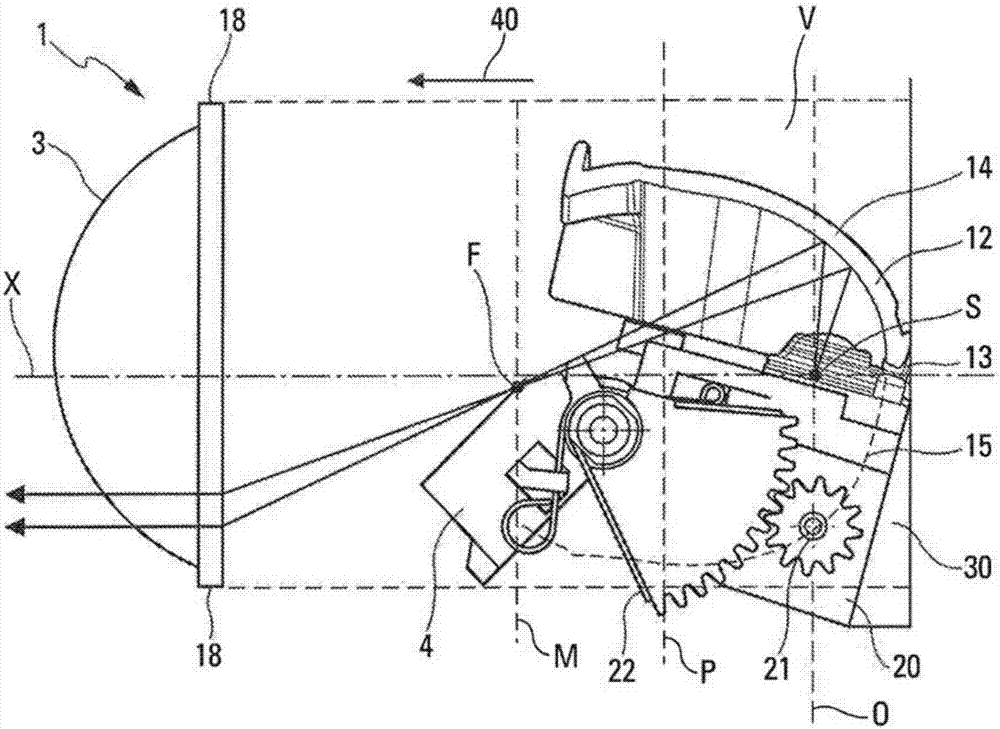
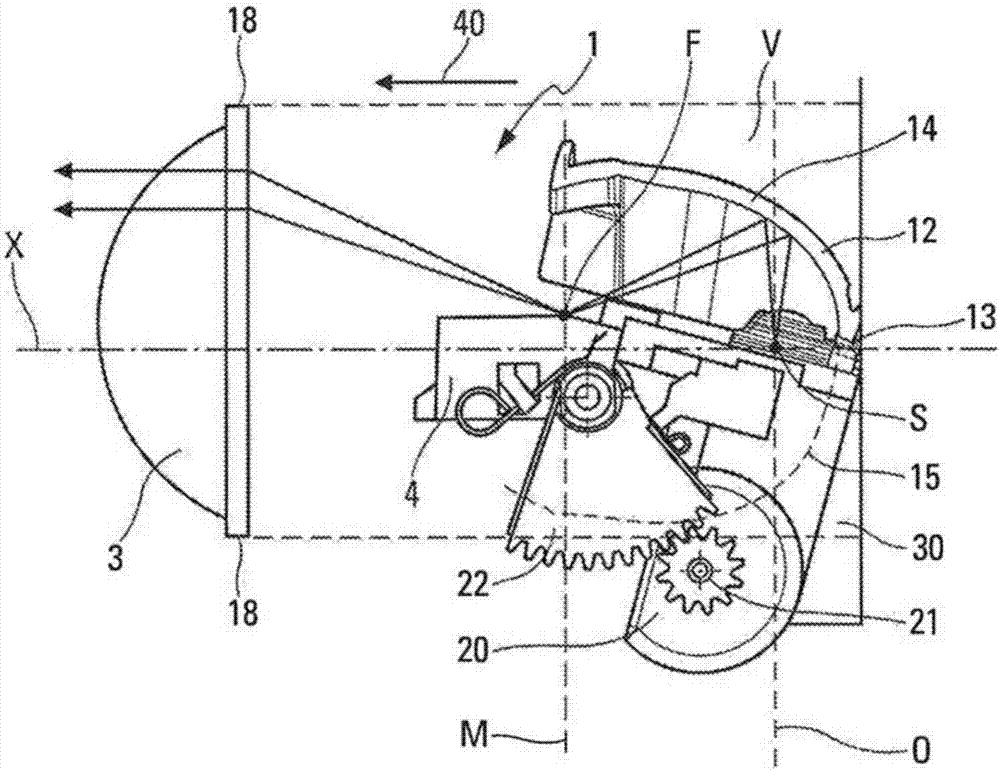
[0030] refer to figure 1 and figure 2 , the drawing shows a semi-elliptical floodlight 1 for a motor vehicle comprising a reflector 12 in the form of a first semi-ellipsoid part extending above the plane of symmetry of the ellipsoid . The floodlight also includes a light source S including a light emitting diode (LED) placed inside the reflective portion. In this case, the light source comprises a plurality of LED diodes. The second semi-ellipsoid part 15 combined with the first semi-ellipsoid part 14 to constitute the ellipsoid part is shown in dotted lines to facilitate understanding, but it does not represent a real physical element of the semi-ellipse floodlight. The second semi-ellipsoid part 15 is symmetrical to the first semi-ellipsoid part 14 about the plane of symmetry of the ellipsoid. The first semi-ellipsoid part is bounded in the axial direction by a plane M which is perpendicular to the axis of symmetry of the ellipsoid and which intersects the ellipsoid.

...


PUM


Abstract

The projector (1) comprises a light source (S), a movement means (20), a moving optical element (4) driven by the movement means (20) to cut and / or reflect a light beam emitted by the source (S), a radiator (30) thermally linked to the movement means (20), and a reflector (12), the light beam being reflected by the reflector (12) before being cut and / or reflected by the moving optical element (4), the reflector (12) having the shape of a portion of a semi-ellipsoid, the source (S) being positioned on the axis of symmetry (X) of the ellipsoid, the radiator (30) being positioned below the plane of symmetry of said ellipsoid, the radiator (30) being situated at least partially inside said ellipsoid between a base (13) of the reflector (12) and the moving optical element (4), and being positioned at least partially within a volume (V) defined by the cylindrical extension, along an optical axis of an optical lens (3), of a peripheral contour of said lens (3) to a transverse plane passing through a base (13) of the reflector (12).

Description

technical field [0001] The field of the invention is that of devices for motor vehicles, more particularly of floodlights for these motor vehicles. Background technique [0002] Motor vehicle floodlights generally comprise a lens and a reflector within which a light source is located. It is known to use blocking strips to enable various stages of blocking the beam. When controlled, the strip is electrically actuated by the motor to move between at least two angular positions in which the strip more or less blocks the light beam. For example, the strip may limit the range of the floodlight, eg to a low beam position to avoid blinding drivers driving in the opposite direction, or to the main beam, where no blocking occurs. Currently, this technique is used with floodlights that include high power light sources, such as those with halogen or xenon lamps, for which the loss of optical power due to the flux being interrupted by the strips is less than cause problems. [0003]...

Claims


Application Information

Patent Timeline
IPC IPC(8): F21S8/10F21V7/10F21V14/04F21V14/08F21V29/70F21W101/10F21Y115/10
CPCF21S41/675F21S41/147F21S41/683F21S45/47F21S41/321F21S41/332F21S41/365
Inventor 哈桑·寇劳西里尔·瑞维尔A·奥布里
Owner AML SYST
Why Eureka
Try Eureka