Liquid-gas separation device

A technology of gas-liquid separator and rotating shaft, which is applied in the direction of separation method, liquid degassing, liquid degassing general arrangement diagram, etc., and can solve the problems such as the reduction of separation efficiency

Active Publication Date: 2019-04-19
LG CHEM LTD
View PDF12 Cites 0 Cited by
  • Summary
  • Abstract
  • Description
  • Claims
  • Application Information

AI Technical Summary

Problems solved by technology

In this case, when the stripper condenses, the separation efficiency decreases

Method used


Image

  • Liquid-gas separation device
  • Liquid-gas separation device
  • Liquid-gas separation device

Examples


Embodiment Construction

[0038] Hereinafter, a gas-liquid separator according to an example of the present invention will be described in detail with reference to the accompanying drawings.

[0039] In addition, the same or similar reference numerals in the drawings denote the same or similar elements regardless of the figure number, and repeated description will not be given. For convenience of description, the size and shape of each illustrated element may be exaggerated or reduced.

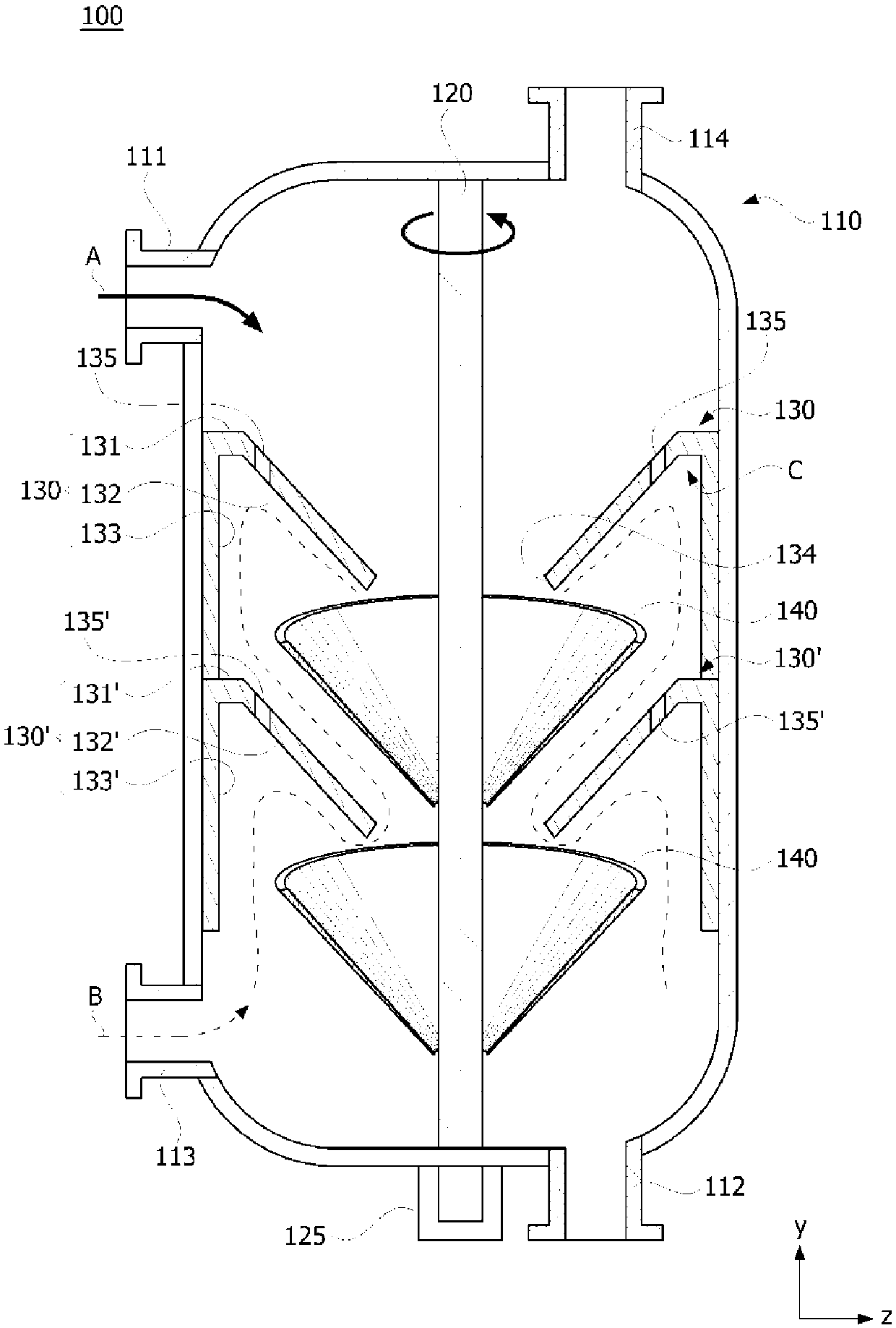
[0040] figure 1 is a sectional view showing a gas-liquid separator 100 according to an example of the present invention.

[0041] In this specification, the gas-liquid separator 100 can make reactant A (also called "first fluid" or "liquid raw material") and steam B (also called "second fluid" or "stripping agent") The process of reacting to remove volatile organic compounds (VOCs) from reactant A.

[0042] Here, a chemical reaction between the first fluid and the second fluid is not necessary. For example, the gas...


PUM


Abstract

The invention relates to a gas-liquid separator. According to one aspect of the present invention, there is provided a gas-liquid separator, which includes: a housing including a first supply part and a second supply part; a rotating shaft rotatably provided on the housing; a drive unit, arranged to rotate the rotating shaft; fixed cones, arranged inside the housing, and each fixed cone includes an inclined area, a first through hole and at least one second through hole, the diameter of the inclined area is along the The direction from the first supply portion to the second supply portion decreases, the first through hole passes the rotation shaft, and the second fluid introduced via the second supply portion passes through the second supply portion. a through hole; and a rotating cone provided inside the housing so as to be spaced apart from the fixed cone and mounted on the rotating shaft so as to rotate around the rotating shaft.

Description

[0001] Cross References to Related Applications [0002] This application claims the benefit of Korean Patent Application No. 10-2014-0181102 filed with the Korean Intellectual Property Office on December 16, 2014, the entire contents of which are incorporated herein by reference. technical field [0003] The present invention relates to a gas-liquid separator, and more particularly, to a gas-liquid separator in which a stripping agent and vaporized volatile organic compounds (VOC) flow smoothly to an upper portion thereof. Background technique [0004] A rotating cone column (SCC) is a gas-liquid separator composed of a multi-stage rotating cone rotating around a rotating axis and a non-rotating fixed cone. The SCC has the advantage of improving the residence time of the feed reactants. [0005] In particular, when the fluid is injected into the upper part of the rotating cone from the upper part of the distillation column, the fluid is spread on the surface of the rotatin...

Claims


Application Information

Patent Timeline
Patent Type & Authority Patents(China)
IPC IPC(8): B01D19/00B01D45/12
CPCB01D19/00B01D45/12B01D19/001B01D19/0026B01D19/0057Y10S55/03B01D19/0068
Inventor 申大荣周垠廷许畅会张诚根申俊浩
Owner LG CHEM LTD
Why Eureka
Try Eureka