air conditioner indoor unit

A technology for air-conditioning indoor units and centrifugal fans, applied in air-conditioning systems, space heating and ventilation, space heating and ventilation details, etc., can solve the problem of deteriorating airflow conditions at the air inlet tongue, affecting the user's use effect, and impeller rotation backflow To achieve the effect of speeding up the air flow, optimizing the wind effect, and smoothing the flow path

Active Publication Date: 2018-10-12
QINGDAO HAIER AIR CONDITIONER GENERAL CORP LTD
View PDF6 Cites 0 Cited by
  • Summary
  • Abstract
  • Description
  • Claims
  • Application Information

AI Technical Summary

Problems solved by technology

[0002] When the existing air-conditioning indoor unit is blowing air, the wind after heat exchange by the heat exchanger is directly blown out from the air outlet provided on the air conditioner under the action of the internal fan, so all the blown wind is heat-exchanged wind, that is, the blown air The wind is either all hot or all cold. Such wind blowing directly on the human body will make people feel extremely uncomfortable
[0003] In addition, the volute of the volute of the centrifugal fan of the existing air-conditioning indoor unit is mostly designed as a shallow tongue, resulting in more exposure of the impeller, which will cause backflow when the impeller rotates, reducing the performance of the fan
At the same time, the air flow angle of the gas flowing out of the impeller will be too large, and the gas will deflect outward along the spiral direction of the volute, and flow directly to the air outlet, which will cause negative pressure at the air inlet tongue of the volute, and deteriorate the air flow at the air inlet tongue. The airflow condition will increase the noise and affect the user's use effect

Method used


Image

  • air conditioner indoor unit
  • air conditioner indoor unit
  • air conditioner indoor unit

Examples


Embodiment Construction

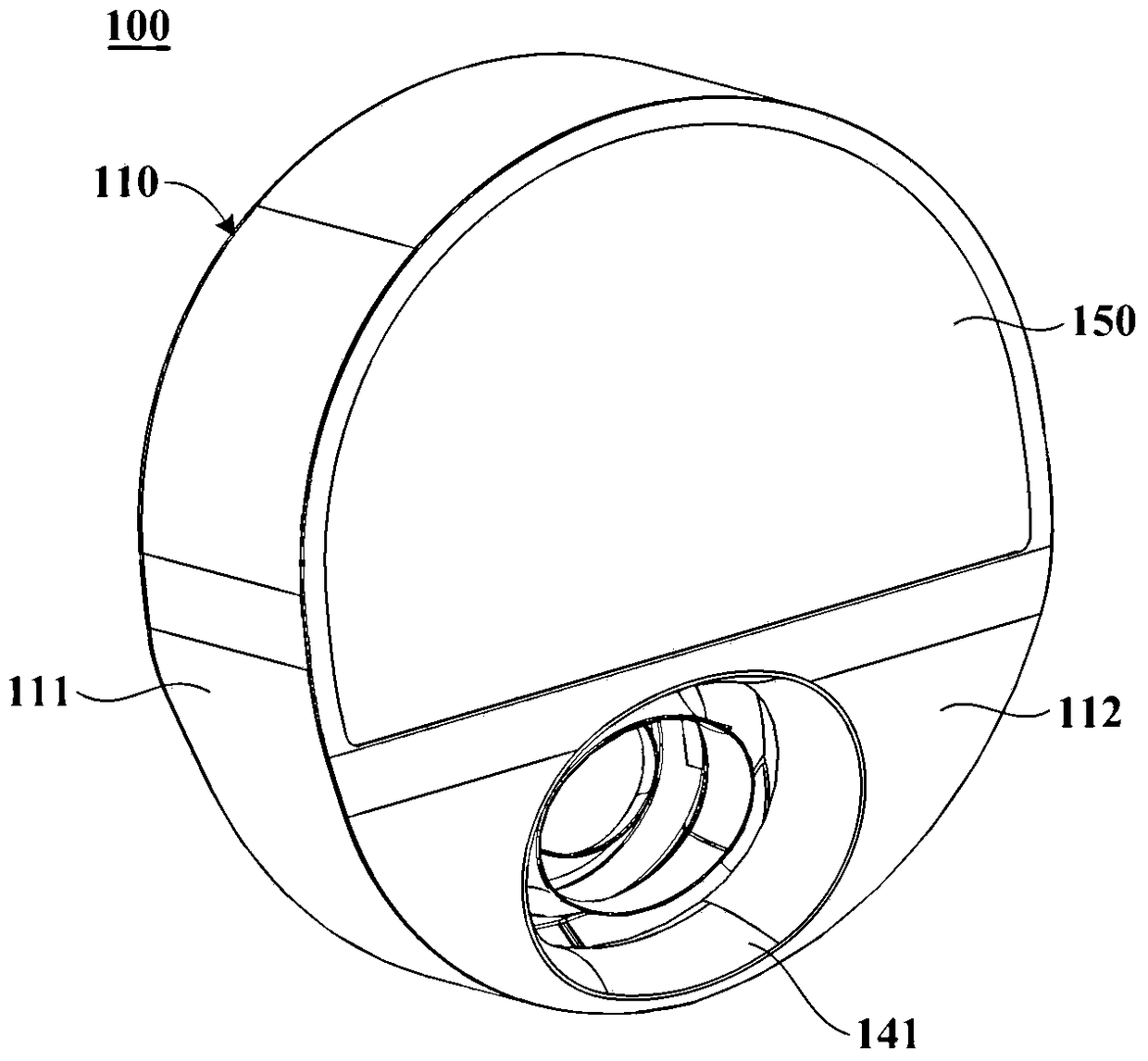
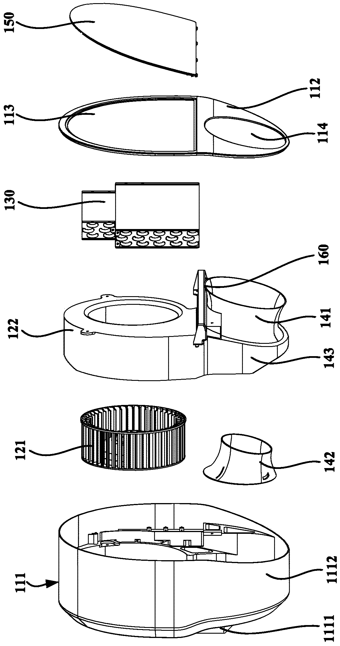
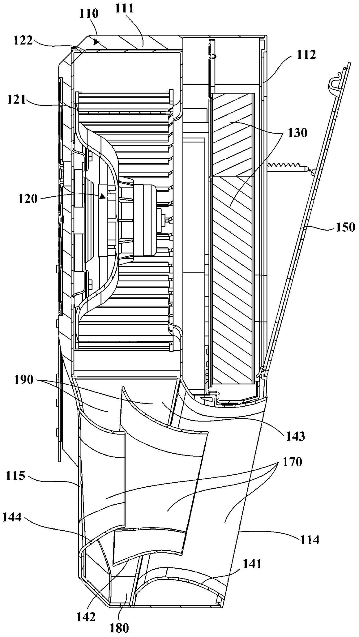
[0055] figure 1 is a schematic structural diagram of an air conditioner indoor unit 100 according to an embodiment of the present invention, figure 2 for figure 1 An exploded view of the air conditioner indoor unit 100 shown, image 3 yes figure 1 The cross-sectional view of the air conditioner indoor unit 100 is shown. see Figure 1 to Figure 3 , the air conditioner indoor unit 100 of the embodiment of the present invention includes: a housing 110 and a centrifugal fan 120 located in the housing 110 and the like.

[0056] Specifically, the casing 110 has a first air inlet 113 and an air outlet 114 . The first air inlet 113 is disposed on the upper part of the housing 110 for introducing air in the environment space (such as indoor air). The air outlet 114 is disposed at the lower part of the casing 110 and is used for blowing air to the environment space.

[0057] The centrifugal fan 120 is disposed on the upper part of the housing 110 , and is configured to suck ambi...


PUM


Abstract

The invention provides an air conditioner indoor unit. The indoor unit comprises a shell and a centrifugal fan, wherein the shell is provided with a first air inlet and an air outlet, and the centrifugal fan is arranged on the upper portion of containing space inside the shell and comprises a volute and an impeller arranged in the volute; the volute comprises a volute front wall and a volute peripheral wall, and a fan air inlet communicated with the first air inlet is formed in the volute front wall; the volute peripheral wall comprises a worm-shaped section gradually expanded relative to the outer contour of the impeller, and the two ends of the worm-shaped section extend downwards to form a worm tongue section and an outlet section; the projection of the worm tongue section in the plane perpendicular to the rotation axis of the centrifugal fan is a circular-arc worm tongue projection line; the projection of the outer contour of the impeller in the plane is a round impeller projection line; and the included angle between the connecting line of the round center of the worm tongue projection line and the round center of the impeller projection line and the horizontal line extending to the direction close to the worm tongue projection line from the round center of the impeller projection line ranges from 70 degrees to 80 degrees. The air conditioner indoor unit is large in air outlet quantity and very low in noise.

Description

technical field [0001] The invention relates to the technical field of air conditioning, in particular to an air conditioner indoor unit. Background technique [0002] When the existing air-conditioning indoor unit is blowing air, the wind after heat exchange by the heat exchanger is directly blown out from the air outlet provided on the air conditioner under the action of the internal fan, so all the blown wind is heat-exchanged wind, that is, the blown air Wind or all is hot wind, or is all cold wind, and such wind directly blows on people's health and can make people feel extremely uncomfortable. [0003] In addition, the volute of the volute of the centrifugal fan of the existing air-conditioning indoor unit is mostly designed as a shallow tongue, resulting in more exposure of the impeller, which will cause backflow when the impeller rotates, reducing the performance of the fan. At the same time, the air flow angle of the gas flowing out of the impeller will be too larg...

Claims


Application Information

Patent Timeline
Patent Type & Authority Patents(China)
IPC IPC(8): F24F1/00F24F13/08F24F13/24
CPCF24F1/0022F24F13/081F24F13/24F24F2013/247
Inventor 戴现伟王永涛闫宝升单翠云关婷婷
Owner QINGDAO HAIER AIR CONDITIONER GENERAL CORP LTD
Why Eureka
Try Eureka