Heat storage fluidized combustion furnace for treating VOCs waste gas adsorbing solid waste

A solid waste, boiling combustion technology, applied in the direction of combustion method, combustion type, incinerator, etc., can solve the problems of inability to guarantee purification conditions, material layer can not be too thick, coking and other problems

Active Publication Date: 2017-08-01
山东天盛纤维素股份有限公司
View PDF8 Cites 2 Cited by
  • Summary
  • Abstract
  • Description
  • Claims
  • Application Information

AI Technical Summary

Problems solved by technology

[0003] Example 1 of the prior art uses two combustion methods to incinerate (pyrolyze) solid waste (garbage), trying to increase the residence time of the furnace and the second combustion chamber to ensure effective decomposition of pollutants. As we all know, the moisture content of garbage is relatively low. High, during the combustion process of the furnace, its moisture forms superheated steam and is discharged with the flue gas. In addition, the N in the air 2 It is also a non-combustible part, which will take away a lot of heat and cause the temperature of the furnace to drop. In other words, the heat load of garbage fuel is low, which will inevitably lead to low combustion temperature of garbage in the furnace and the secondary combustion chamber. If it is in the secondary combustion chamber (rising chamber, flue) Arranging the heating surface will not guarantee the purification conditions required by the "Standards for Pollution Control of Domestic Waste Incineration" GB 18485-2014, that is, the incineration temperature in the furnace is ≥850°C, and the residence time of flue gas at this temperature is ≥2s, which is very easy to cause difficulty in disposal Large, harmful to the environment, heavy dioxin pollutants, etc.
Moreover, the furnace and the secondary combustion chamber are far apart in the plane layout of the equipment, so particles are easily deposited in the flue connecting the two. On the one hand, it causes high-temperature corrosion of the flue; The working environment changes from negative pressure to positive pressure, allowing pollutants to leak from the furnace
The circulating fluidized bed garbage incineration boiler designed in the second example of the prior art has the following disadvantages: the first is that compared with the existing circulating fluidized bed boiler, the change is that the heating parts such as the membrane water wall in the middle and the lower part of the furnace are cancelled, so that To ensure the temperature of the furnace, the advantage is to ensure that the garbage can continue to burn (pyrolysis), and the disadvantage is that the material layer (fluidized layer) should not be too thick. A thicker material layer will store heat and burn here, resulting in uneven fluidization and local high temperature. Coking will occur, but if the material layer is too thin, the furnace temperature will not reach the effective pyrolysis temperature (≥850°C) due to insufficient thermal load of waste fuel; the second is to assume that the temperature in the lower part of the furnace reaches the effective pyrolysis temperature (≥850°C) ℃), the heat load of waste fuel is sufficient, and the middle and lower part of the furnace is not equipped with membrane water cooling wall, so the air supply volume of the air chamber is required to be increased to prevent the furnace from coking. The cost will be greatly increased, and it also means that the excess air coefficient will increase and the total amount of pollutants will be discharged. Surface metal components are washed and worn by particles, and the flue gas contains Cl - , SO 2 Pollutants such as pollutants are the main cause of high-temperature corrosion of metal components on the heating surface
Existing Art Example 3 The molten salt in the molten salt regenerator mainly acts as a heat storage and heat conductor, and it is difficult to apply it to the technical field of solid waste pyrolysis

Method used


Image

  • Heat storage fluidized combustion furnace for treating VOCs waste gas adsorbing solid waste
  • Heat storage fluidized combustion furnace for treating VOCs waste gas adsorbing solid waste
  • Heat storage fluidized combustion furnace for treating VOCs waste gas adsorbing solid waste

Examples


Embodiment Construction

[0026] The present invention will be further described below in conjunction with the accompanying drawings and specific embodiments.

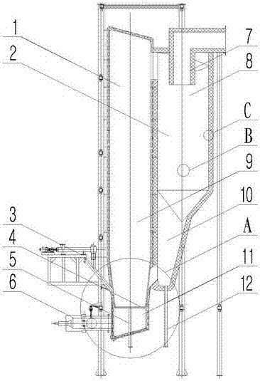
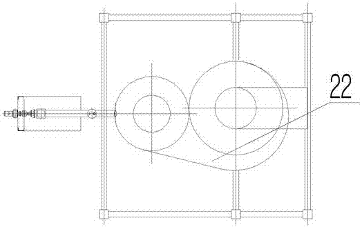
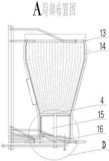
[0027] Such as figure 1 , figure 2 , image 3 , Figure 4 , Figure 5 , Figure 6 , Figure 7 As shown, a regenerative fluidized combustion furnace for treating and adsorbing VOCs waste gas and solid waste is characterized in that it includes a furnace 1 , a regenerative return chamber 2 , and a screw feeding assembly 3 .

[0028] The furnace 1 includes a furnace body 9, a water-cooled air distribution plate 4, a water-cooled air chamber assembly 11, an ignition burner 6, and a slag discharge pipe 5. The water-cooled air chamber assembly 11 includes a cylindrical water-cooled wall 14, an upper header 13. The lower header 16, the water-cooled air distribution plate 4, and the air chamber 15. The water-cooled air distribution plate 4 includes a water-cooled pipe 18, an air distribution plate 17, and a wind cap 19. A part of the water-cool...


PUM


Abstract

The invention relates to the technical field of volatile organic compound waste gas treatment, in particular to a heat storage fluidized combustion furnace for treating VOCs waste gas adsorbing solid waste. The heat storage fluidized combustion furnace is characterized by comprising a hearth, a heat storage return chamber and a spiral feeding assembly. The device is low in manufacturing cost and meets the treatment requirements of different departments which discharge VOCs waste gas adsorbing solid waste, waste does not need to be conveyed to departments having the solid waste treating ability to be treated, the logistical and treatment cost is reduced, and meanwhile pollutant omission and scattering, odor leakage, drop leakage and other phenomena are avoided in the conveying process.

Description

technical field [0001] The invention relates to the technical field of waste gas treatment of volatile organic compounds, in particular to a thermal storage fluidized combustion furnace for treating adsorbed VOCs waste gas and solid waste. Background technique [0002] Gaseous pollutants emitted by industry are the main source of atmospheric environmental pollutants, among which volatile organic compound waste gas (VOCs) is a gaseous pollutant that is seriously harmful to the environment, and it is also an occupational hazard that affects the health of operators in the workplace It is widely derived from chemical industries such as paints, coatings, coatings, lubricants, and rubber. Due to its huge destructive effect on the human body and the natural environment, the country has issued relevant laws and regulations to strictly control its governance and emissions. At present, the commonly used treatment methods of organic waste gas treatment technology include combustion me...

Claims


Application Information

Patent Timeline
Patent Type & Authority Applications(China)
IPC IPC(8): F23G5/30F23G5/44
CPCF23G5/30F23G5/44F23G2203/501
Inventor 杨松
Owner 山东天盛纤维素股份有限公司
Why Eureka
Try Eureka