Novel micro-cantilever array cyclic scanning system

A technology of micro-cantilever and cyclic scanning, which is applied in the field of micro-beam scanning system, can solve the problems of data instability, different energy, and difficulty in signal recognition, and achieve the effect of avoiding light interference and improving accuracy

Inactive Publication Date: 2017-07-21
ANHUI UNIV OF SCI & TECH
View PDF7 Cites 3 Cited by
  • Summary
  • Abstract
  • Description
  • Claims
  • Application Information

AI Technical Summary

Problems solved by technology

At present, the single micro-cantilever biochemical sensor used in large quantities can only use one experiment at a time, which wastes a lot of time; and because of the need for reference sample control in the biochemical reaction, this is to conduct experiments with multiple micro-cantilever beams in the same environment. There is an urgent need to realize simultaneous detection and research of multiple microbeams; using a laser to irradiate the microbeam array and detect the bending signal of each microbeam is a current research hotspot at home and abroad.
[0003] In the patent literature with the publication number CN101278357A, a "system and method for detecting micro-mechanical and nano-mechanical structures" is disclosed, which uses a voice coil motor to drive a laser to scan each beam on the array; however, the laser is long Time movement will bring some unstable factors to the system; if it drives the pool to move, it will bring higher requirements to the voice coil motor of the system, and at the same time, it will cause the particles in the reaction solution in the pool to move, which will bring about data instability.
[0004] The patent document with the application number 2014200942732 discloses a "micro-cantilever beam deflection detection system based on the micro-cantilever beam array sensor based on plane mirror reflection"; it proposes to use the laser to change direction in the air to realize the scanning and detection of the deflection of the array micro-beam, and to realize The laser and the micro-cantilever beam are fixed, thus eliminating the instability factors caused by movement to a certain extent, but there is a reciprocating translation of the voice coil motor, which puts forward a higher stability for the voice coil motor. At the same time, the reciprocating translation of the voice coil motor brings inconvenience in signal processing and difficulty in signal identification
[0005]Application No. 2014100755444 discloses a micro-cantilever deflection scanning system and scanning method based on a micro-cantilever array sensor based on a multi-angle plane transmission mirror ", also uses the laser to scan and detect the deflection of the array microbeams in the air, and uses the stepper motor to drive the glass that can be transmitted to realize the reciprocating scanning of the microbeams, but after the glass is transmitted, each microbeam will be irradiated The difference in the energy on the surface causes the inconsistency of the experimental conditions

Method used


Image

  • Novel micro-cantilever array cyclic scanning system
  • Novel micro-cantilever array cyclic scanning system
  • Novel micro-cantilever array cyclic scanning system

Examples


Embodiment Construction

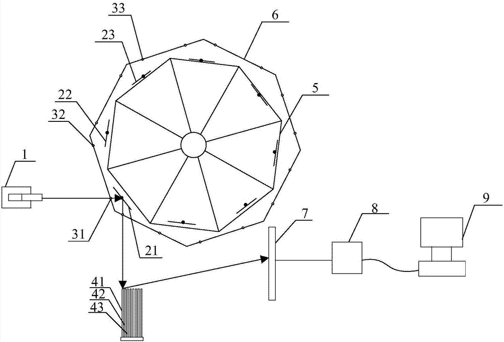
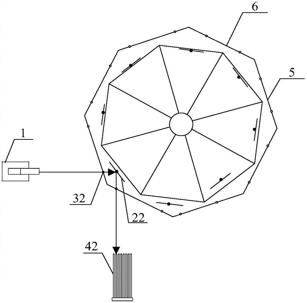
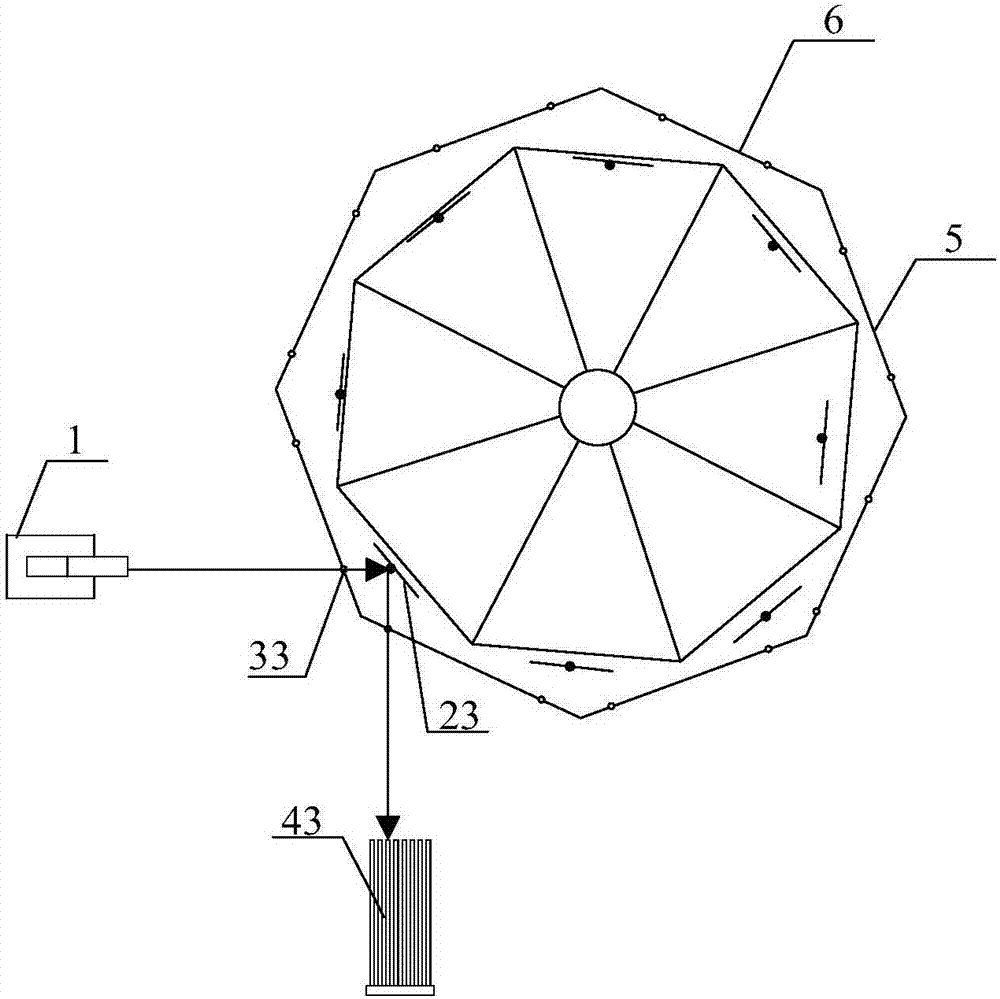
[0024] see figure 1 , figure 2 and image 3 , the structural form of the micro-cantilever beam array cyclic scanning system in the present embodiment is: the structural form of the cyclic scanning system composed of eight scanning units is set as:

[0025] The same fixed laser 1 is used as the shared laser light source of the eight scanning units. The laser 1 fixedly emits a laser beam horizontally. The laser 1 is a semiconductor laser, and the laser light source is a monochromatic light source with a wavelength of 632-780nm.

[0026] Eight micro-cantilever beams are used to form a micro-cantilever beam array, and eight plane mirrors are arranged correspondingly to the eight micro-cantilever beams; the eight plane mirrors are fixedly arranged on different positions of the same rotating platform 5; M plane mirrors Corresponding to a pair of incident and outgoing light holes in turn, drive the shading plate 6 and the rotating table 5 to rotate at the same speed at the same ti...


PUM


Abstract

The invention discloses a novel micro-cantilever array cyclic scanning system which is characterized in that the fixedly arranged same laser acts as the shared laser light source of M scanning units, and the laser fixedly and horizontally emits laser beams; M micro-cantilevers form a micro-cantilever array, and M plane mirrors are arranged for the M micro-cantilevers in a one-to-one correspondence way; the M plane mirrors are fixedly arranged at different positions of the same rotary table; meanwhile, a light shading plate is driven to rotate with the rotary table at the same speed so that the M plane mirrors are enabled to be in the light path of the laser beams one by one along with rotation of the light shading plate and the rotary table, M beams of reflected light of different positions is formed on the M plane mirrors one by one and projected to the free end of each micro-cantilever in the micro-cantilever array in a one-to-one correspondence way to form a micro-cantilever array scanning system, and the light shading plate is driven to cyclically rotate with the rotary table at the same speed and thus cyclic scanning of the micro-cantilever array can be realized. The novel micro-cantilever array cyclic scanning system is easy to establish and easy to control and high in accuracy.

Description

technical field [0001] The invention belongs to the field of micro-beam scanning systems, in particular to a novel micro-cantilever beam array cyclic scanning system. Background technique [0002] Micro-cantilever sensing technology is a sensing method developed rapidly after the emergence of atomic force microscopes and microsystems. As the simplest micro-mechanical component, it has always been a research hotspot in micro-nano sensing technology. At present, the single micro-cantilever biochemical sensor used in large quantities can only use one experiment at a time, which wastes a lot of time; and because of the need for reference sample control in the biochemical reaction, this is to conduct experiments with multiple micro-cantilever beams in the same environment. There is an urgent need to realize simultaneous detection and research of multiple microbeams; using a laser to irradiate the microbeam array and detect the bending signal of each microbeam is a current researc...

Claims


Application Information

Patent Timeline
Patent Type & Authority Applications(China)
IPC IPC(8): G01Q10/00
CPCG01Q10/00
Inventor 薛长国牛晓燕张飞张涛钢方菲沙博胡业林闵凡飞
Owner ANHUI UNIV OF SCI & TECH
Why Eureka
Try Eureka