Semiconductor layout structure

A layout structure, semiconductor technology, applied in the direction of semiconductor devices, semiconductor/solid-state device components, transistors, etc., can solve the problems of increasing the complexity of the manufacturing process and the cost of the manufacturing process, and reduce the complexity of the manufacturing process, reduce the manufacturing cost, The effect of simplifying pattern design

Active Publication Date: 2017-07-14
UNITED MICROELECTRONICS CORP
View PDF5 Cites 4 Cited by
  • Summary
  • Abstract
  • Description
  • Claims
  • Application Information

AI Technical Summary

Problems solved by technology

It can be seen that the multi-patterning method is a precise manufacturing process that requires extremely high manufacturing process control, so the adoption of the multi-patterning method inevitably increases the complexity and cost of the manufacturing process.

Method used


Image

  • Semiconductor layout structure
  • Semiconductor layout structure
  • Semiconductor layout structure

Examples


Embodiment Construction

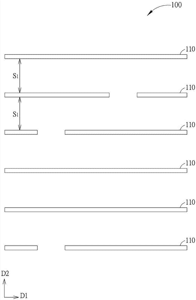
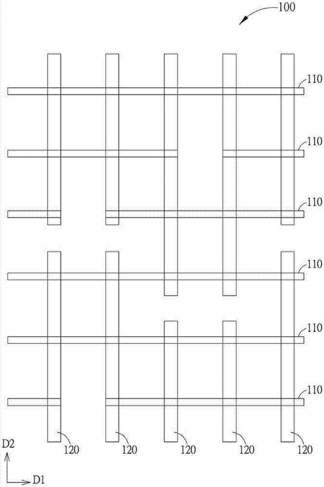
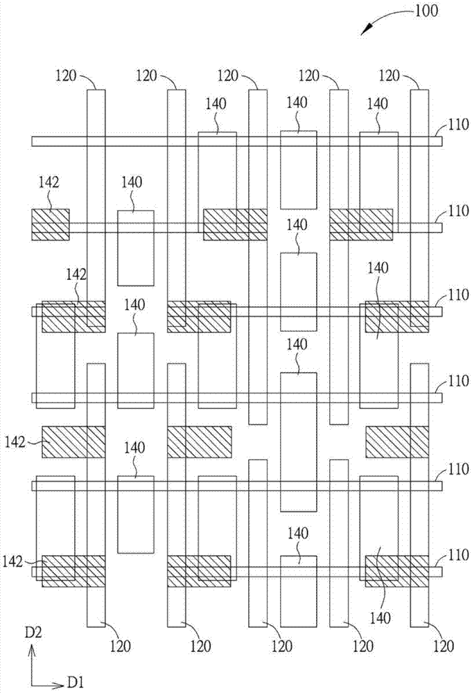
[0042] Persons familiar with this technology should understand that the following provides a number of different embodiments to disclose different features of the present invention, but not limited thereto. In addition, the drawings disclosed below are simplified to express the features of the present invention more clearly, so the drawings disclosed below do not show all the elements of a specified element (or device). In addition, the diagrams disclosed below are idealized schematic diagrams according to the present invention, so variations from these schematic diagrams, such as differences due to manufacturing techniques and or tolerances, are predictable. Therefore, the disclosure of the present invention should not be limited to the specific shapes disclosed in the following figures, but should also include deviations in shapes caused by manufacturing techniques.

[0043] In addition, those familiar with the technology should understand that in the following descriptions,...


PUM


Abstract

The invention discloses a semiconductor layout structure. The semiconductor layout structure comprises at least one first signal line and a pair of low-power supply potential lines, wherein the first signal line and the low-power supply potential lines extend along a first direction, the low-power supply potential lines are arranged along a second direction, the first direction and the second direction are perpendicular to each other, and more importantly, the low-supply potential lines are formed at two opposite sides of the first signal line.

Description

technical field [0001] The present invention relates to a semiconductor layout structure, in particular to a semiconductor layout structure that can be completed by using multiple patterning in a semiconductor back-end-of-line (BEOL) process. Background technique [0002] In the manufacturing process of semiconductor integrated circuits, the manufacture of the microstructure of integrated circuits requires the use of photolithography in appropriate substrates or material layers such as semiconductor substrates / film layers, dielectric material layers, or metal material layers. And etching and other manufacturing processes to form tiny patterns with precise dimensions. To achieve this goal, the existing semiconductor technology forms a mask layer (mask layer) on a target material layer, so that these tiny patterns are formed / defined in the mask layer, and then the patterns are transferred to the target film layer . In general, the mask layer may include a patterned photoresi...

Claims


Application Information

Patent Timeline
Patent Type & Authority Applications(China)
IPC IPC(8): H01L27/02H01L27/088
CPCH01L27/0203H01L27/0886H01L23/5286H01L27/0207H01L23/5226H01L23/528
Inventor 黄俊宪郭有策王淑如
Owner UNITED MICROELECTRONICS CORP
Why Eureka
Try Eureka