Thermal jet printing head based on graphene-carbon nanotube composite structure and preparation method thereof

A carbon nanotube composite and carbon nanotube technology, which is applied in printing and other directions, can solve the problems of unstable closing, high contact resistance, and easy contamination of the printing chamber by UV curing glue, and achieve the effect of complete microfluidic structure.

Active Publication Date: 2018-06-12
HUAZHONG UNIV OF SCI & TECH
View PDF8 Cites 0 Cited by
  • Summary
  • Abstract
  • Description
  • Claims
  • Application Information

AI Technical Summary

Problems solved by technology

[0007] (1) The carbon nanotube microbubble generator uses a metal electrode, and there is a Schottky barrier between the two, and the contact resistance is large
[0008] (2) The microfluidic structure adopts a combination of wet etching and dry etching, which is not easy to control the processing accuracy
[0009] (3) The depth of the ink inlet channel is the same as that of the inkjet printing unit, and there is a problem that the bubble valve is not closed firmly when the liquid inlet is closed
[0010] (4) The double microbubble generator and the microfluidic structure adopt the UV curing bonding method, and the bonding strength is limited; and the coating of the UV curing glue is easy to pollute the printing chamber

Method used


Image

  • Thermal jet printing head based on graphene-carbon nanotube composite structure and preparation method thereof
  • Thermal jet printing head based on graphene-carbon nanotube composite structure and preparation method thereof
  • Thermal jet printing head based on graphene-carbon nanotube composite structure and preparation method thereof

Examples


preparation example Construction

[0074] The preparation method of the above-mentioned thermal jet printing head mainly includes the following steps:

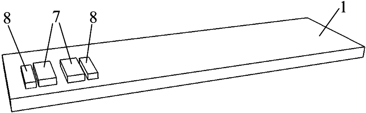
[0075] In the first step, a graphene-carbon nanotube composite structure microbubble generator and a carbon nanotube temperature sensor array are prepared on a glass substrate;

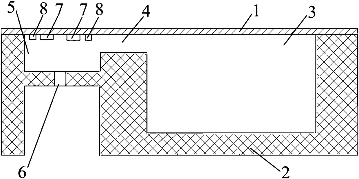
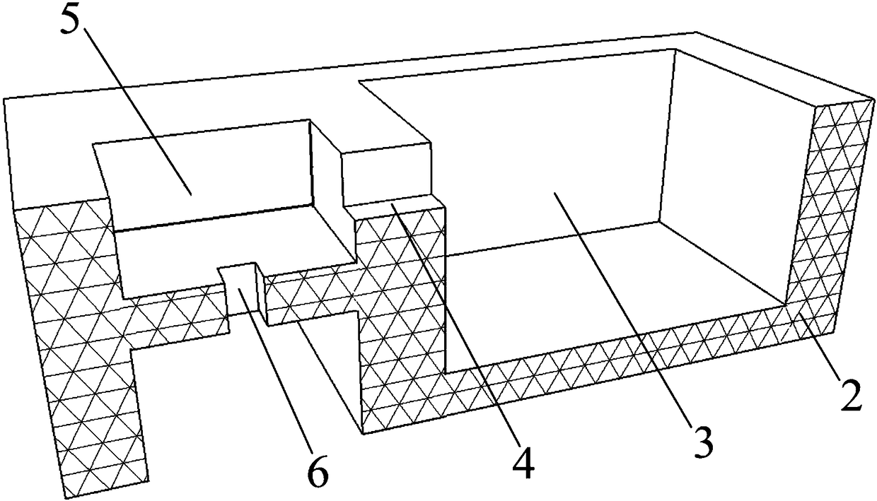
[0076]In the second step, the microfluidic structure is prepared on the silicon wafer by using the ICP process and the surface planarization process of PDMS (polydimethylsiloxane) to fill the deep groove; the microfluidic structure includes the main channel, the inkjet chamber, the ink inlet channels, nozzles, inkjet channels;

[0077] In the third step, the glass and silicon wafers are bonded using an anodic bonding process with graphene fragments as the intermediate layer. The bonding method is shown in Figures 9 and 10. The graphene fragments 9 are located between the glass substrate 1 and the silicon substrate 2. High pressure and high temperature are applied to the glass substrat...

Embodiment 1

[0110] (1) Using quartz glass as the substrate, the quartz glass is cleaned, and the graphene-carbon nanotube composite structure microbubble generator and carbon nanotube temperature sensor array are prepared on the quartz glass. The process is as follows:

[0111] (1.1) Magnetron sputtering is used to form a nickel film with a thickness of 100nm, and nickel electrodes are formed by using the existing stripping process; the distance between the nickel electrodes of the temperature sensor is 2 μm, and the width is 4 μm;

[0112] (1.2) The graphene grown by CVD on the copper foil is transferred to the glass substrate by the wet transfer process of spin-coated PMMA, and the graphene electrode of the microbubble generator is prepared through the RIE etching of photolithography and oxygen; the graphene electrode of the graphene electrode The pitch is 2 μm and the width is 4 μm;

[0113](1.3) Mix carbon nanotubes with absolute ethanol solvent at a ratio of 0.001mg / ml, and disperse ...

Embodiment 2

[0132] (1) Using Pyrex7740 type glass as the substrate, the glass is cleaned, and the microbubble generator and temperature sensor based on the graphene-carbon nanotube composite structure are prepared on the quartz glass, and the process is as follows:

[0133] (1.1) Magnetron sputtering is used to form a titanium film with a thickness of 200nm, and a titanium test electrode is formed by using the existing stripping process;

[0134] (1.2) Adopt the wet transfer process of spin-coated PMMA to transfer the graphene grown by CVD on the copper foil to the glass substrate, and prepare the graphene electrode of microbubble generator and temperature sensor through photolithography and RIE etching of oxygen; The pitch is 6 μm and the width is 5 μm;

[0135] (1.3) Mix the carbon nanotubes and absolute ethanol solvent at a ratio of 0.05 mg / ml, and disperse the carbon nanotubes evenly by ultrasound; apply an AC voltage of 1 MHz, 16 V between the titanium electrodes on the glass, and us...


PUM

PropertyMeasurementUnit
thicknessaaaaaaaaaa
thicknessaaaaaaaaaa
widthaaaaaaaaaa

Abstract

The invention discloses a thermal jet-printing head based on a graphene-carbon nanotube composite structure, and a preparation method thereof. An ICP process and a surface smoothing process of filling deep grooves with PDMS are adopted, and a main channel, an ink jet chamber, an ink inlet channel, a nozzle and an ink jet channel are prepared in a silicon underlayer; and an anodic bonding process is adopted, graphene pieces are taken as a middle layer, and a glass substrate is bonded with the silicon underlayer. The main channel communicates with the ink jet chamber through the ink inlet channel, the depth of the ink inlet channel is less than the depth of the ink jet chamber; the nozzle is formed in the bottom of the ink jet chamber; and a microbubble generator array with a carbon nanotube-graphene composite structure and a carbon nanotube temperature sensor array are prepared in an area corresponding to the ink jet chamber, of the glass substrate, and arranged in a manner of facing the ink jet chamber. The jet head is reliable in liquid inlet closure, high in bonding strength, not liable to pollute a jet-printing chamber, and capable of easily controlling accuracy during preparation.

Description

technical field [0001] The invention belongs to the technical field of MEMS thermal jet printing, and more specifically relates to a thermal jet printing head based on a graphene-carbon nanotube composite structure and a preparation method thereof. Background technique [0002] Inkjet printing imaging technology has become the preferred color hard copy technology for large-format digital inkjet printing, digital photo printing, digital printing, digital color proofing, and home and office color output systems, and has been widely used and achieved great commercial success. In addition to inkjet printing, jet printing technology can also provide non-contact micro-dispensing of various liquids, which has a very wide range of applications, such as: biofluid printing, making color filters for liquid crystal displays, digitally making PCBs, drug injections and Fuel injection and more. It is also expected to provide a bottom-up, simple and effective implementation for the constru...

Claims


Application Information

Patent Timeline
Patent Type & Authority Patents(China)
IPC IPC(8): B41J2/16
CPCB41J2/1601
Inventor 周文利朱宇陈昌盛向耘宏蒋履辉喻研王耘波高俊雄
Owner HUAZHONG UNIV OF SCI & TECH
Why Eureka
Try Eureka