
An intelligent flame cutting machine

A flame cutting machine and cutting head technology, applied in the direction of gas flame welding equipment, metal processing equipment, welding equipment, etc., can solve the problems of reducing cutting accuracy, displacement of raw materials, winding of gas pipes, etc., and achieve the effect of enhancing retraction , reduce scrap rate, improve the effect of compaction area

Active Publication Date: 2019-06-21
CHANGSHA JIANXIN MACHINERY MFG
View PDF6 Cites 0 Cited by
  • Summary
  • Abstract
  • Description
  • Claims
  • Application Information

AI Technical Summary

Problems solved by technology

[0003] At present, the existing flame cutting machine places the raw material on the cutting table and cuts it by the cutting head. However, after the raw material is placed on the cutting table, there is no corresponding fixing device to fix the raw material. During the cutting process, the raw material may be Displacement will occur, reducing the accuracy of cutting, thereby increasing the scrap rate; in addition, when the cutting head is constantly moving and cutting, the air pipe connected to it will move with the cutting head, and it is still possible to simply adopt the method of hanging wire It leads to the entanglement of the air pipe, which makes it stuck, so the existing way of retracting the air pipe is not effective

Method used


Image

  • An intelligent flame cutting machine
  • An intelligent flame cutting machine
  • An intelligent flame cutting machine

Examples

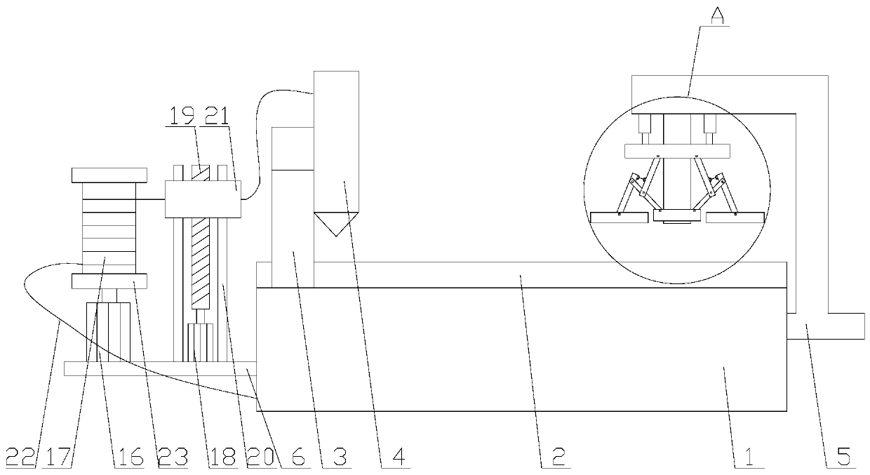

Embodiment Construction

[0025] The present invention is described in further detail now in conjunction with accompanying drawing. These drawings are all simplified schematic diagrams, which only illustrate the basic structure of the present invention in a schematic manner, so they only show the configurations related to the present invention.

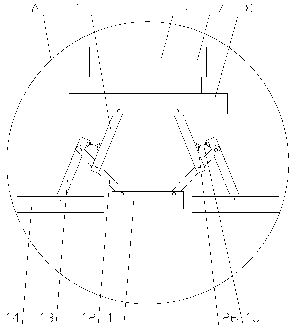
[0026] Such as Figure 1-4 As shown, an intelligent flame cutting machine includes a base 1, a cutting table 2, a cutting bridge 3 and a cutting head 4. The base 1 also includes a pressing mechanism and a wire take-up mechanism, and the pressing mechanism is located on the cutting table. 2, the base 1 is provided with a first bracket 5, the pressing mechanism is connected with the base 1 through the first bracket 5, the wire take-up mechanism is located on one side of the cutting head 4, and the base 1 is provided with There is a second bracket 6, and the take-up mechanism is connected to the base 1 through the second bracket 6;

[0027] The pressing mechani...


PUM


Abstract

The invention relates to an intelligent flame cutting machine. The intelligent flame cutting machine comprises a base, a cutting table, a cutting bridge and a cutting head; the base is provided with a pressing mechanism and a wire collecting mechanism; the pressing mechanism includes a cylinder, a driving plate, a support column, a fixed ring and a pressing module; the pressing module includes two pressing units; the pressing units include first support rods, second support rods, third support rods, pressing plates and connecting ropes; and the wire collecting mechanism includes a first motor, a wire collecting shaft, a second motor, a lead screw, a slide rod and a slide block. In the intelligent flame cutting machine, after raw materials are placed on the cutting table, the raw materials are fixed on the cutting table through the pressing mechanism; the pressing mechanism can increase the pressing area, so that the stability of the raw materials is improved, the cutting precision is improved, and the reject rate is reduced; in addition, gas transmission pipes are stored and freely collected and placed as needed through the wire collecting mechanism, so that the gas transmission pipes are not liable to wind; and the wire collecting mechanism can prevent blockage of the gas transmission pipes to improve the collecting and placing effects.

Description

technical field [0001] The invention relates to the field of cutting equipment, in particular to an intelligent flame cutting machine. Background technique [0002] Flame cutting machine is a kind of cutting equipment that uses gas with oxygen or gasoline with oxygen to cut metal materials. Mainly used in heavy industry. [0003] At present, the existing flame cutting machine places the raw material on the cutting table, and the cutting head cuts it. However, after the raw material is placed on the cutting table, there is no corresponding fixing device to fix the raw material. During the cutting process, the raw material may be Displacement will occur, reducing the accuracy of cutting, thereby increasing the scrap rate; in addition, when the cutting head is constantly moving and cutting, the air pipe connected to it will move with the cutting head, and it is still possible to simply adopt the method of hanging the wire Cause the winding of air delivery pipe, thereby make i...

Claims


Application Information

Patent Timeline
Patent Type & Authority Patents(China)
IPC IPC(8): B23K7/00B23K7/10
CPCB23K7/00B23K7/10
Inventor 施淑琴
Owner CHANGSHA JIANXIN MACHINERY MFG
Learn More