
Porous silicon negative electrode material covered by composite carbon and preparing method thereof

A negative electrode material, porous silicon technology, applied in the direction of battery electrodes, structural parts, electrical components, etc., can solve the problems affecting the coulombic efficiency of the battery, the looseness of the graphene coating layer, the impact of silicon cycle, etc., to achieve coulombic efficiency and avoid direct Contact, the effect of ensuring the effective capacity

Inactive Publication Date: 2017-07-07
SHANDONG UNIV
View PDF7 Cites 29 Cited by
  • Summary
  • Abstract
  • Description
  • Claims
  • Application Information

AI Technical Summary

Problems solved by technology

[0005] But silicon also has an Achilles' heel: ① As a semiconductor material, silicon is far less conductive than graphite
②The silicon material is dense, and compared with the relatively fluffy graphite, the penetration ability of lithium ions is poor
Although this invention improves the rate performance of the material through the compounding of silicon and graphene, the problem of direct contact between silicon and electrolyte still exists. performance degradation
[0008] In the previous patent "a graphene-coated porous silicon material and its preparation method", the applicant of this patent used the in-situ reduction of aluminum to realize the coating effect of graphene on porous silicon particles, but in the subsequent dealloying During the chemical reaction, the reaction between aluminum and acid will generate a large amount of hydrogen gas, and the removal of hydrogen gas will partly cause the loosening of the graphene coating layer on the silicon surface. During the subsequent battery cycle, part of the electrolyte will still enter the material. The interior of the silicon, affecting the cycle of silicon
[0009] To sum up, in the prior art, problems such as the poor electrical conductivity of the porous silicon negative electrode material itself, the sharp reduction in battery capacity caused by the dramatic volume change in the electrochemical deintercalation during charging and discharging, and the reaction with the electrolyte affecting the Coulombic efficiency of the battery have not yet been solved. lack of effective solutions

Method used


Image

  • Porous silicon negative electrode material covered by composite carbon and preparing method thereof
  • Porous silicon negative electrode material covered by composite carbon and preparing method thereof
  • Porous silicon negative electrode material covered by composite carbon and preparing method thereof

Examples


Embodiment 1

[0057] (1) Preparation of alloy microspheres

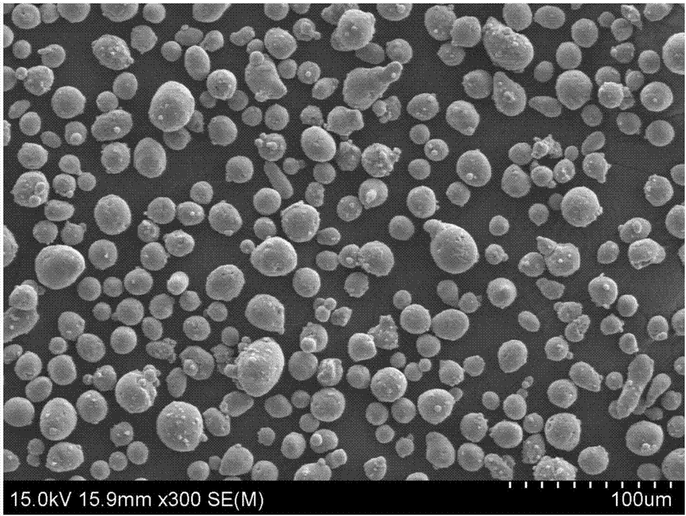
[0058] First, prepare an aluminum-silicon alloy with a mass fraction of silicon of 10%, and melt magnesium and silicon in proportion. The melting temperature is 800°C. After the alloy ingot is obtained, it is sprayed. The atomization temperature is 1000°C. By controlling the air flow and the material Ratio, to obtain Al-Si alloy spheres with a median diameter of 20um.

[0059] (2) De-alloying of micro-alloy balls and the first layer of carbon coating

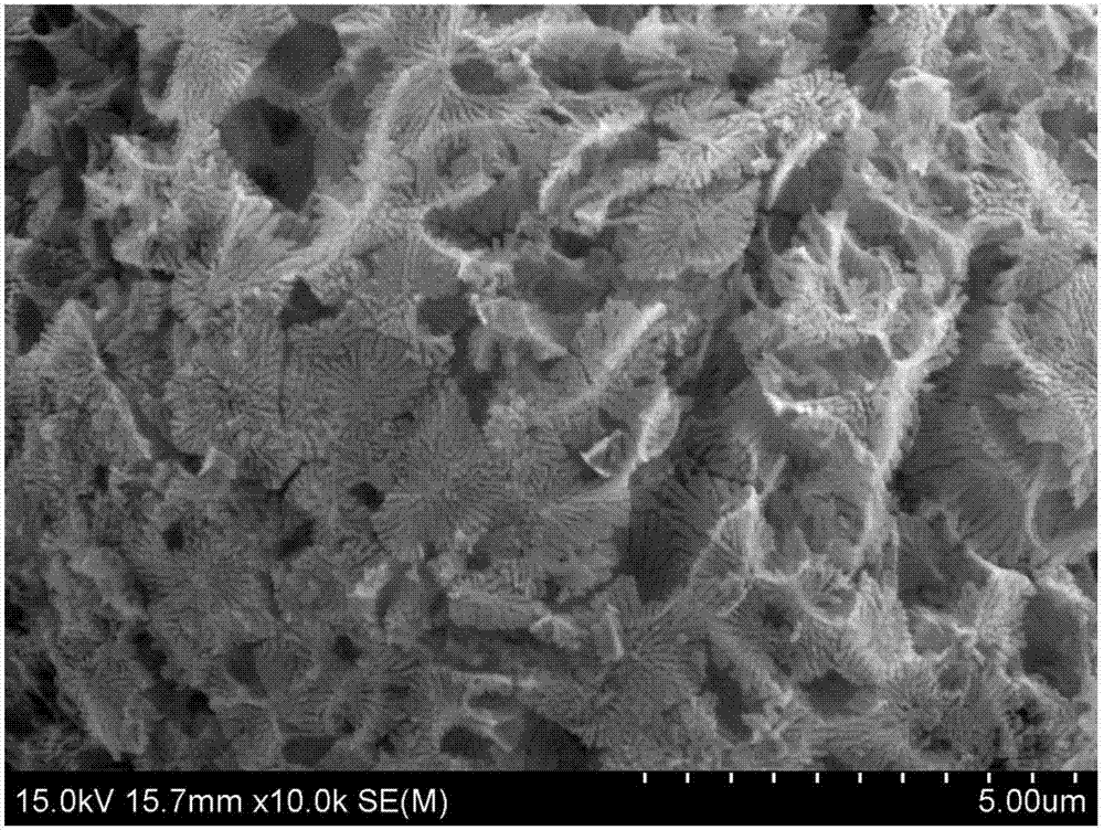
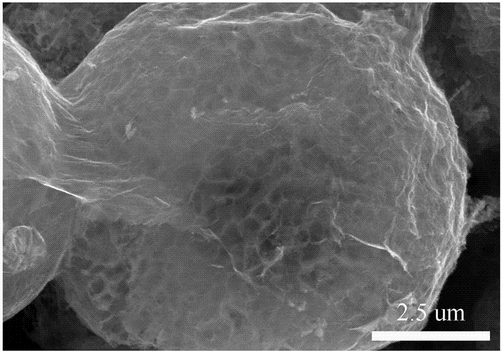
[0060] Put the alloy ball obtained in step (1) into the graphene oxide aqueous solution with a concentration of 1mg / mL, the magnesium in the alloy will fully reduce the graphene oxide, and after reacting for 1h, add the obtained coated sample to the concentration In 1mol / L hydrochloric acid, corrode to obtain graphene-coated porous silicon.

[0061] (3) The second layer of carbon coating

[0062] The graphene-coated porous silicon obtained in step (2) is added to the tetrahydrofu...

Embodiment 2

[0064] (1) Preparation of alloy microspheres

[0065] Firstly, a magnesium-silicon alloy with a silicon mass fraction of 10% is prepared, and the magnesium and silicon are smelted in proportion. The melting temperature is 700°C. After the alloy ingot is obtained, it is sprayed. The atomization temperature is 700°C. By controlling the air flow and the material Ratio, to obtain a magnesium-silicon alloy ball with a median diameter of 10um.

[0066] (2) De-alloying of micro-alloy balls and the first layer of carbon coating

[0067] Put the alloy ball obtained in step (1) into the graphite oxide aqueous solution with a concentration of 0.5mg / mL, the magnesium in the alloy will fully reduce the graphene oxide, and after reacting for 1h, add the obtained coated sample to the concentration In 0.2mol / L hydrochloric acid, corrode to obtain graphene-coated porous silicon.

[0068] (3) The second layer of carbon coating

[0069] The graphene-coated porous silicon obtained in step (2) ...

Embodiment 3

[0071] (1) Preparation of alloy microspheres

[0072] First, an aluminum-silicon alloy with a silicon mass fraction of 10% is prepared, and the melting temperature is 750°C. After the alloy ingot is obtained, it is sprayed, and the ratio of the air flow to the material is adjusted to obtain an aluminum-silicon alloy ball with a median diameter of 10um.

[0073] (2) De-alloying of micro-alloy balls and the first layer of carbon coating

[0074] Add the alloy balls obtained in step (1) into hydrochloric acid with a concentration of 1 mol / L, and fully corrode to obtain porous silicon. The obtained porous silicon is put into a citric acid alcohol solution with a mass fraction of 10%, and after being fully stirred, the above-mentioned sample is dried by spray drying, and the obtained sample is put into a carbonization furnace, nitrogen is used as a protective atmosphere, 700 ℃ carbonization for 5h.

[0075] (3) The second layer of carbon coating

[0076] The carbon-coated porous...


PUM


Abstract

The invention discloses a porous silicon negative electrode material covered by a composite carbon layer and a preparing method thereof. On the basis of porous silicon after dealloying, the first covering of loose carbon and overall covering of exterior high-density carbon are achieved by covering a compounded carbon layer in which graphene and the high-density carbon are combined or low-density carbon and the high-density carbon are combined, interior low-density carbon can improve interior electrical conductivity of a whole micron structure, and the exterior high-density carbon can well prevent an electrolyte from penetrating through the carbon layer and entering the interior of micron particles, accordingly well solve the problem that a silicon material reacts with a battery liquid, ensure a high coulombic efficiency, and accordingly well ensure cycle performance of a battery. According to the porous silicon negative electrode material covered by the composite carbon layer and the preparing method thereof, a core innovation point is double carbon layer covering, and the silicon / carbon / carbon composite negative electrode material is prepared by combining the low-density carbon and the high-density carbon.

Description

technical field [0001] The invention relates to the preparation of battery electrode materials, in particular to a composite carbon-coated porous silicon negative electrode material and a preparation method thereof. Background technique [0002] In recent years, electronic equipment is developing toward intelligence, multi-function and portability, and the requirements for battery technology are getting higher and higher. First, light electronic devices require light batteries to keep the overall mass of the device at a low level. Secondly, the capacity of the battery should be high enough to meet the long-term operation of electronic equipment. Therefore, the high specific energy lithium-ion battery industry came into being. Lithium-ion batteries have become ideal supporting power sources for portable electronics, mobile products, and electric vehicles due to their high voltage, high specific energy, long cycle life, and environmental friendliness. [0003] Lithium-ion b...

Claims


Application Information

Patent Timeline
Patent Type & Authority Applications(China)
IPC IPC(8): H01M4/36H01M4/38H01M4/583H01M10/0525
CPCH01M4/366H01M4/386H01M4/583H01M10/0525Y02E60/10
Inventor 慈立杰翟伟
Owner SHANDONG UNIV
Learn More