
Friction stir welding method for aluminum alloy having changeable thickness

A technology of friction stir welding and welding method, which is applied in welding equipment, metal processing, non-electric welding equipment, etc., and can solve problems such as shortening of stirring needle length, affecting welding, and backing plate damage, so as to expand the application range, improve economic benefits, The effect of saving production cost

Inactive Publication Date: 2017-06-30
SHANGHAI AEROSPACE EQUIP MFG GENERAL FACTORY
View PDF7 Cites 8 Cited by
  • Summary
  • Abstract
  • Description
  • Claims
  • Application Information

AI Technical Summary

Problems solved by technology

[0008] 1) Throughout the welding length, if the material thickness at a local position is greater than the original standard thickness of the plate, conventional friction stir welding may produce welding defects such as incomplete penetration or weak connection (or "kissing") when welding to this position; Moreover, when welding this position, the undercut of the stirring tool may be too large, resulting in a large flash, which is prone to tunnel defects;
[0009] (2) If the thickness of the material at a local location is less than the original standard thickness of the plate, conventional friction stir welding cannot form a welded joint with a beautiful surface when it is welded to this location, and welding defects such as surface grooves and furrows are likely to occur; During the welding process, human interference with the welding pressure will cause the stirring needle of the stirring tool to rub against the backing plate, resulting in shortening of the length of the stirring needle and damage to the backing plate, which will directly affect subsequent welding

Method used


Image

  • Friction stir welding method for aluminum alloy having changeable thickness

Examples


Embodiment Construction

[0032] Now in conjunction with embodiment, accompanying drawing, the present invention will be further described:

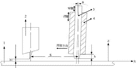
[0033] figure 1 It is a schematic diagram of implementation of friction stir welding welding method for aluminum alloy sheets with variable thickness. After the laser measurement accuracy of the laser tracker 2 is calibrated by the distance in the height direction, it can measure the thickness of the aluminum alloy sheet in the forward direction of welding in real time, and feed back the measurement data to The numerical control system of the friction stir welding equipment, the numerical control system processes and analyzes the measurement data in real time, and the numerical control system drives the welding shaft in real time according to the feedback data, so as to realize the control of the penetration depth of the stirring needle 3 of the split stirring tool, and then realize the welding depth control to realize the friction stir welding of aluminum alloy ...


PUM


Abstract

The invention discloses a friction stir welding method for an aluminum alloy sheet having changeable thickness. The friction stir welding method comprises the following implementation steps of mounting a laser tracking instrument within a certain distance range in front of a stirring tool; monitoring the thickness of a material sheet in a real-time manner; enabling acquired data to be fed back to a friction stir welding digital control system by an information control system; enabling the acquired data to be processed by the digital control system in time, and enabling the processed data to be fed back to a friction stir welding equipment driving system in a real-time manner; and performing real-time on-line control on the split type stirring tool by the driving system, so as to realize the friction stir welding of the aluminum alloy sheet having changeable thickness. According to the friction stir welding method disclosed by the invention, the welding depth of the split type stirring tool is controlled in a real-time manner, so that defects of being lack of through welding or damages generated by the stirring tool and the base plate which are liable to generate during the process of the friction stir welding method for the aluminum alloy sheet having changeable thickness can be effectively avoided.

Description

technical field [0001] The patent of the invention belongs to the field of solid-phase welding of metal materials, and relates to a friction stir welding method under the condition of uneven thickness of aluminum alloy thin plates. Background technique [0002] Friction stir welding is a new solid-phase welding method. Since its invention in 1991, it has been widely used in the connection technology of aluminum alloys, magnesium alloys, copper alloys and other light alloys. Friction stir welding has the advantages of high weld quality, no defects such as pores and cracks caused by conventional fusion welding, small welding stress and deformation, high welding quality stability, friction stir welding equipment has strong operability, and the use of numerical control system can effectively Reduce the impact of human factors on welding quality. [0003] At present, friction stir welding has achieved relatively successful application cases in welding aluminum alloy sheets, whet...

Claims


Application Information

Patent Timeline
IPC IPC(8): B23K20/12B23K20/26
CPCB23K20/123B23K20/26B23K2101/18B23K2103/10
Inventor 吉华杨国舜汪虎张晓进陈大伟周礼龙
Owner SHANGHAI AEROSPACE EQUIP MFG GENERAL FACTORY
Learn More