Multifunctional friction welding table
A multi-functional, friction welding technology, applied in welding equipment, non-electric welding equipment, metal processing equipment, etc., can solve problems such as low work efficiency
- Summary
- Abstract
- Description
- Claims
- Application Information
AI Technical Summary
Problems solved by technology
Method used
Image
Examples
Embodiment 1
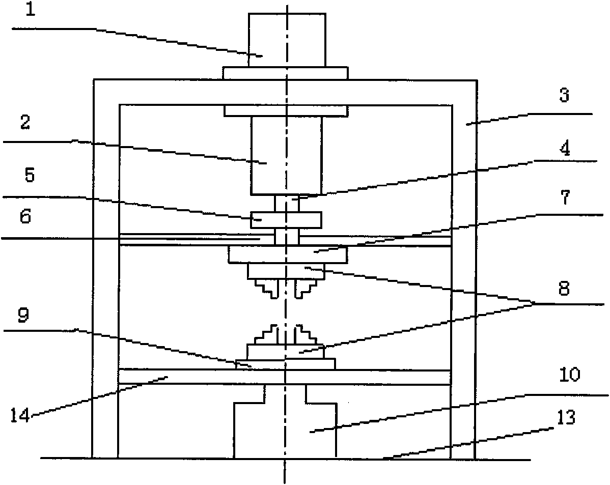
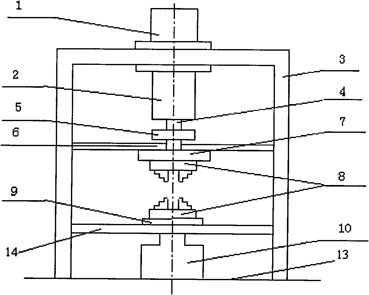
[0013] Embodiment 1: A multifunctional friction welding table, including a motor 1, a clutch brake combination 2, a gantry frame 3, a main shaft 4, a coupling 5, a first partition 6, a flywheel disc 7, and a weldment clamping end 8. Workbench 9, hydraulic system 10, bottom plate 13 and second partition 14. The entire multifunctional friction welding table is fixed on the gantry 3, the first partition 6 and the second partition 14 are fixedly connected to the brackets on both sides of the gantry 3, and the motor 1 is located on the top of the gantry 3 and placed perpendicular to the ground , The motor shaft faces downward, the flywheel disc 7 is under the first partition 6, one end of the coupling 5 passes through the first partition 6 and is fixed on the upper surface of the flywheel disc 7, and the lower surface of the flywheel disc 7 is fixedly connected to the weldment The upper end of the clamping end 8 and the other end of the coupling 5 are fixedly connected to the main ...
Embodiment 2
[0014] Embodiment 2: Realize continuous drive friction welding on a multifunctional friction welding table. The workpieces to be welded are respectively held on the weldment clamping ends 8 at the upper and lower ends, the motor 1 is turned on, and the motor spindle 4 is driven to rotate and accelerate to a predetermined speed. The horizontal workbench 9 of the transmission rises, so that the two workpieces move toward each other, the end faces are contacted and plasticized under the action of friction, the clutch and brake combination 2 is started to realize the brake, and the clutch in the clutch and brake combination 2 is opened. The hydraulic system 10 increases the axial pressure to perform upset forging and completes the welding.
[0015] Continuous drive friction welding of carbon steel. Grind and clean the end faces of Φ20mm carbon steel to be connected. The carbon steel workpieces to be welded are respectively held on the weldment clamping ends 8 at the upper and low...
Embodiment 3
[0017] Embodiment 3: Inertial friction welding is realized on a multifunctional friction welding table. The workpieces to be welded are respectively held on the weldment clamping ends 8 at the upper and lower ends, the motor 1 is turned on, and the motor main shaft 4 is driven to rotate, so that the flywheel disc 7 is accelerated to a predetermined speed, and the clutch brake combination 2 is used to disconnect the clutch, so that The flywheel disc 7 is separated from the main shaft 4, and the flywheel disc 7 rotates freely with the upper workpiece. At the same time, the hydraulic system 10 is activated to raise the horizontal worktable 9 driven by the screw, and press the lower workpiece to the upper rotating workpiece, so that the joint surface is under pressure. Friction against each other; as the speed of the flywheel disc 7 decreases, the kinetic energy on the flywheel disc 7 is transformed into heat energy required for welding. Before the rotation stops, the axial pressur...
PUM
 Abstract
Description
Claims
Application Information
 - R&D Engineer
- R&D Manager
- IP Professional
- Industry Leading Data Capabilities
- Powerful AI technology
- Patent DNA Extraction
Browse by: Latest US Patents, China's latest patents, Technical Efficacy Thesaurus, Application Domain, Technology Topic, Popular Technical Reports.
© 2024 PatSnap. All rights reserved.Legal|Privacy policy|Modern Slavery Act Transparency Statement|Sitemap|About US| Contact US: help@patsnap.com


