A Plasma Flow Control Device for Drag Reduction of Airships in Near Space

A technology of flow control and plasma, applied in the direction of rigid spacecraft, etc., can solve the problems of large surface area of ​​the hull, drag reduction, plasma intensity, limited area, etc., and achieve reduced airship resistance, high density, and large plane area uniform effect

Active Publication Date: 2019-11-29
CHINA ACAD OF AEROSPACE AERODYNAMICS
View PDF4 Cites 0 Cited by
  • Summary
  • Abstract
  • Description
  • Claims
  • Application Information

AI Technical Summary

Problems solved by technology

[0004] At present, methods such as surface DC corona discharge, atmospheric pressure uniform glow discharge, and surface dielectric barrier discharge, which are often used in plasma flow control technology, all have the disadvantages of the intensity of the generated plasma and the limited area, which cannot meet the requirements of airships in adjacent spaces. Requirements for drag reduction with large surface area of ​​hull

Method used


Image

  • A Plasma Flow Control Device for Drag Reduction of Airships in Near Space
  • A Plasma Flow Control Device for Drag Reduction of Airships in Near Space
  • A Plasma Flow Control Device for Drag Reduction of Airships in Near Space

Examples


Embodiment Construction

[0019] Below in conjunction with accompanying drawing, the present invention is described in further detail:

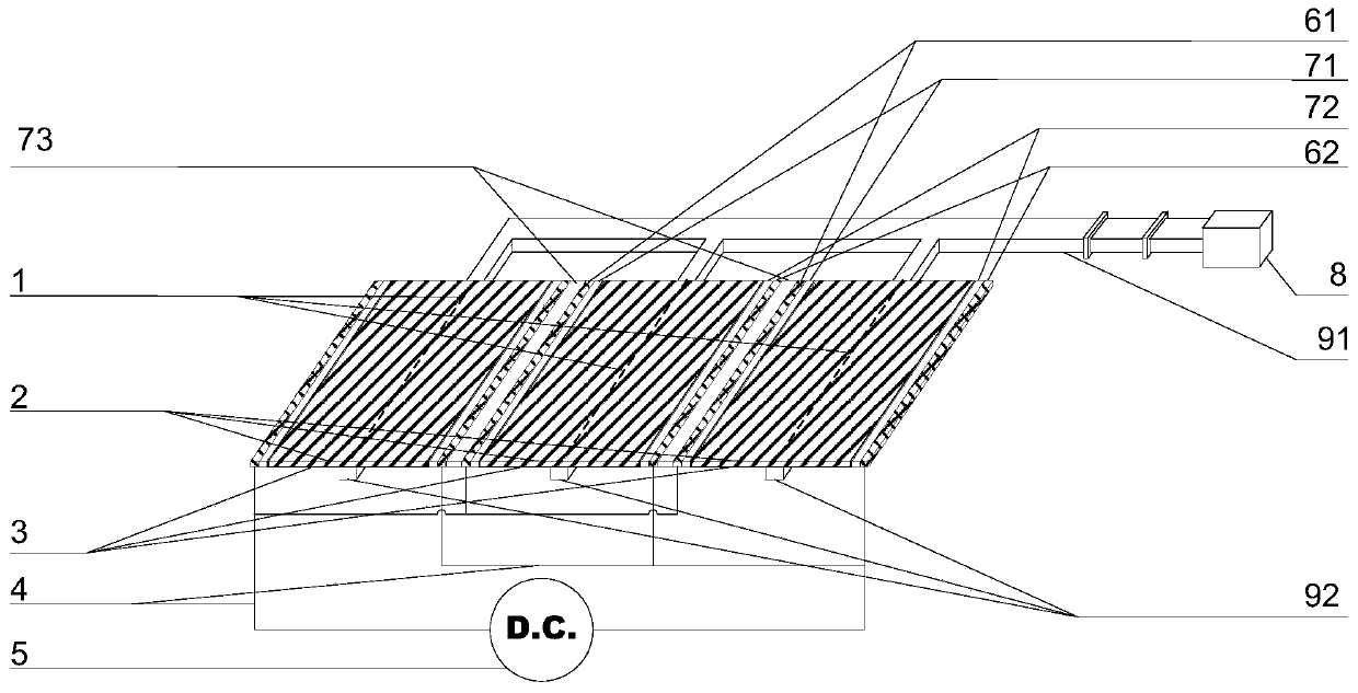
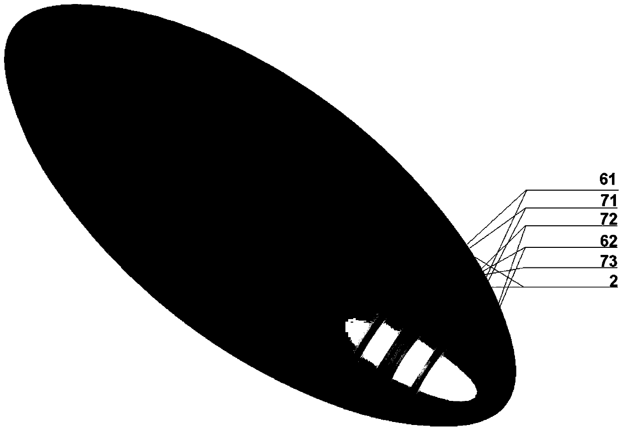
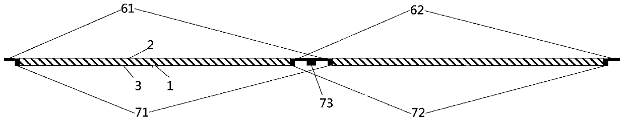
[0020] figure 1 It is a structural schematic diagram of the plasma flow control device for airship drag reduction in adjacent space according to the present invention. Such as figure 1 As shown, the plasma flow control device for airship drag reduction in adjacent space includes: a drag reduction unit, a wire 4 , a DC power supply 5 , a third insulating layer 73 , a microwave generator 8 and a first waveguide 91 . in,

[0021] The drag reducing unit includes a slot antenna 1, a quartz glass plate 2, a metal film 3, a first insulating layer 71, a second insulating layer 72, a first electrode 61, a second electrode 62 and a second waveguide 92, wherein the metal film 3 Plated on the lower surface, left side and right side of the quartz glass plate 2; the metal film 3 plated on the lower surface of the quartz glass plate 2 has a slit, and the slot antenna 1 is embedde...


PUM


Abstract

The invention discloses a plasma flow control device for near space airship resistance reduction. The plasma flow control device comprises a plurality of resistance reduction units, wires, a direct current power supply, a third insulation layer, a microwave generator and a first waveguide. The resistance reduction units comprise slot antennas, quartz glass plates, metal films, first insulation layers, second insulation layers, first electrodes, second electrodes and second waveguides. All the resistance reduction units are sequentially connected through the third insulation layer. The first waveguide is connected with second waveguides and the microwave generator. According to the plasma flow control device, microwaves are transmitted through the slot antennas below the quartz glass plates, uniform waves of a large area are formed on the surfaces of the quartz glass plates to excite surface wave plasma, and the plasma flow control device has the advantages of being high in the density of produced plasma, uniform in plane large area, high in discharging stability and repeatable in treatment process.

Description

technical field [0001] The invention relates to the field of plasma flow control, in particular to a plasma flow control device for drag reduction of an airship in adjacent space. Background technique [0002] Compared with aircraft or satellites, airships in near space have many advantages such as wide ground coverage, long time in the air, strong rapid response capability, low manufacturing and operating costs, reusable, fast upgrading, and good operating characteristics. Application prospects. Therefore, the development of near-space airships is of high urgency. When the flight resistance of the airship is reduced by 1%, the payload can be increased by about 10%, which can greatly improve the flying speed of the aircraft, increase the flight range, and increase the airship time of the airship. [0003] Plasma flow control is a new flow control technology, which has become an important research hotspot in the field of aerodynamics and aerothermodynamics in the world in r...

Claims


Application Information

Patent Timeline
Patent Type & Authority Patents(China)
IPC IPC(8): B64B1/06
CPCB64B1/06
Inventor 胡宁胡远思陈思聪时晓天
Owner CHINA ACAD OF AEROSPACE AERODYNAMICS
Why Eureka
Try Eureka