
A multi-directional vibration energy harvesting device

A vibration energy harvesting, multi-directional technology, applied in electromechanical devices, electrical components, etc., can solve the problem of low collection efficiency of multi-directional energy harvesting energy harvesters, and achieve the effect of improving overall performance, efficient energy harvesting, and low vibration intensity

Active Publication Date: 2019-04-16
XIAMEN UNIV
View PDF6 Cites 0 Cited by
  • Summary
  • Abstract
  • Description
  • Claims
  • Application Information

AI Technical Summary

Problems solved by technology

[0006] The purpose of the present invention is to solve the problem that the vibration energy harvester cannot realize multi-directional energy collection in any plane, which leads to low collection efficiency of the energy harvester, and invents an energy harvesting device that can efficiently obtain multi-directional vibration energy to make up for the aforementioned background technology The defect that can only achieve multi-directional energy harvesting in a single or limited plane

Method used


Image

  • A multi-directional vibration energy harvesting device
  • A multi-directional vibration energy harvesting device

Examples


Embodiment 1

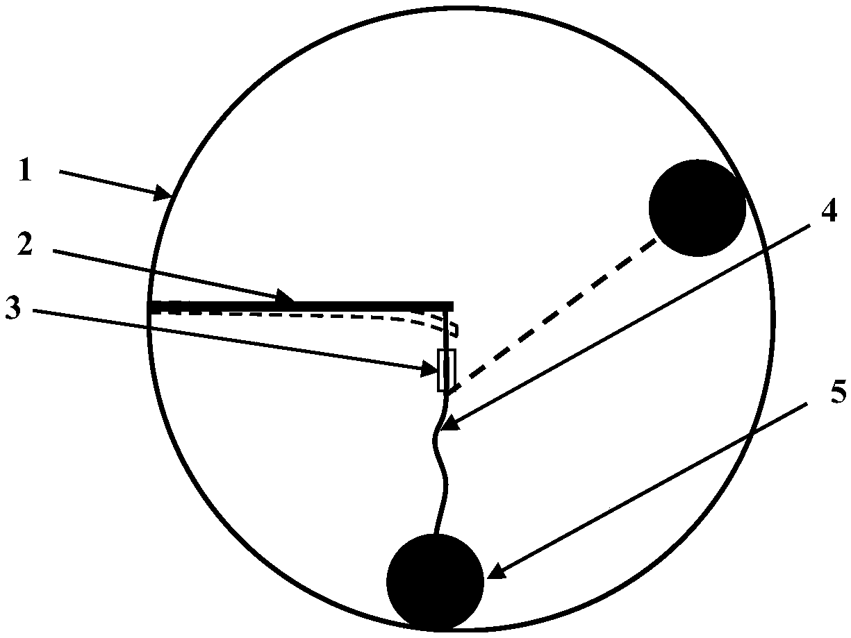
[0024] combine figure 1 As shown, the present invention provides a multi-directional vibration energy collection device, which includes a spherical fixed cavity 1 , an energy conversion device 2 , a conduit 3 , a traction structure 4 and a rolling ball 5 .

[0025] One end of the energy conversion device 2 is connected to the inner wall of the spherical fixed cavity 1, and the other end is a free end; the traction structure 4 passes through the conduit 3, one end is connected to the free end of the energy conversion device 2, and the other end is connected to the rolling ball 5; the rolling ball 5 is against the inner wall of the spherical fixed cavity 1;

[0026] When the external excitation in any direction acts on the device, the spherical fixed cavity 1 and the rolling ball 5 will move relative to each other, so that the rolling ball 5 will drive the traction structure 4 to swing, and at the same time, the conduit 3 will maintain relative to the energy conversion device 2 ...

Embodiment 2

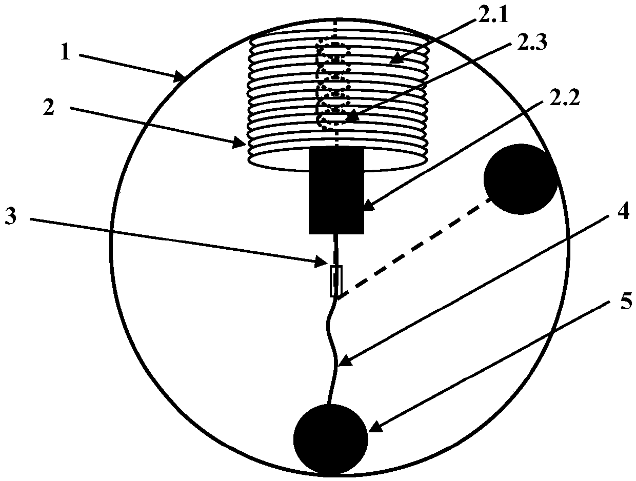
[0037] combine figure 2 As shown, the present invention provides a multi-directional vibration energy collection device, which includes a spherical fixed cavity 1 , an energy conversion device 2 , a conduit 3 , a traction structure 4 and a rolling ball 5 .

[0038] The spherical fixed cavity 1 has a resonant cavity; one end of the energy conversion device 2 is connected to the inner wall of the resonant cavity, and the other end is a free end; the traction structure 4 passes through the conduit 3, and one end is connected to the energy conversion device, and the other end is a free end. One end is connected to the rolling ball 5; when the excitation in any direction of the outside world acts on the device, the spherical fixed cavity 1 and the rolling ball 5 will move relative to each other, and the conduit 3 will convert the momentum of the rolling ball 5 in any direction into acting on the device. The unidirectional impact force of the energy conversion device 2, the tractio...


PUM


Abstract

The invention provides a novel multi-directional vibration energy collection device. The device comprises a spherical fixing cavity, an energy conversion device, a guide pipe, a traction structure and a ball. One end of the energy conversion device is connected with the inner wall of the spherical fixing cavity, and the other end of the energy conversion device is a free end; the traction structure penetrates through the guide pipe, one end of the traction structure is connected with the free end of the energy conversion device, the other end of the traction structure is connected with the ball, and the ball abuts against the inner wall of the spherical fixing cavity; when outside excitation in any direction acts on the device, the spherical fixing cavity moves relative to the ball, so that the ball drives the traction structure to swing; meanwhile, the guide pipe is kept static relative to the energy conversion device; therefore, the guide pipe converts kinetic energy of the ball in any direction into single-direction impact force acting on the energy conversion device, the traction structure drives the energy conversion device to generate electric energy, and multi-directional energy collection in a three-dimensional plane is achieved.

Description

technical field [0001] The invention belongs to the field of micro-energy collection, and in particular relates to a three-dimensional multi-directional vibration energy collection device that is based on a three-dimensional sphere and uses a traction structure to efficiently convert mechanical energy of a multi-directional vibration source in the environment into electrical energy. Background technique [0002] At present, low-power electronic devices such as wireless sensors rely on traditional batteries to provide energy, but traditional batteries have disadvantages such as limited life, difficulty in replacement in harsh environments, and large size that limit the further miniaturization of micro-sensors. In order to solve these problems, the researchers proposed an energy harvester that can absorb vibration energy from the surrounding environment, effectively solving the difficulties of limited battery life and inconvenient replacement. [0003] The main types of vibrat...

Claims


Application Information

Patent Timeline
Patent Type & Authority Patents(China)
IPC IPC(8): H02K35/02
CPCH02K35/02
Inventor 秦利锋张金惠邵俊孙庆强陈文芗周伟
Owner XIAMEN UNIV
Learn More