
A Holographic Display Method for Augmented Reality Based on Complex Amplitude Modulation

An augmented reality and holographic display technology, applied in the field of holographic display, can solve problems such as augmented reality display obstacles, and achieve the effects of eliminating reconstructed image speckle, improving image quality, and enhancing image contrast.

Active Publication Date: 2019-02-01
南京芯视半导体有限公司
View PDF3 Cites 0 Cited by
  • Summary
  • Abstract
  • Description
  • Claims
  • Application Information

AI Technical Summary

Problems solved by technology

However, due to the limitations of technology and devices, there are still some obstacles to realize the real three-dimensional, large viewing angle, and real-time computing augmented reality display on wearable devices.

Method used


Image

  • A Holographic Display Method for Augmented Reality Based on Complex Amplitude Modulation
  • A Holographic Display Method for Augmented Reality Based on Complex Amplitude Modulation
  • A Holographic Display Method for Augmented Reality Based on Complex Amplitude Modulation

Examples


Embodiment 1

[0040] An augmented reality holographic display method based on complex amplitude modulation, comprising the following steps:

[0041] (1) Lay out the display system.

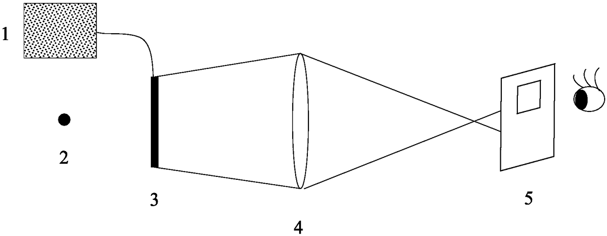
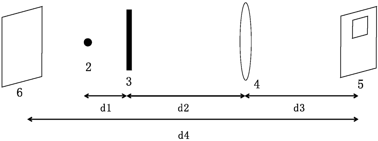
[0042] Such as figure 1 As shown, the point light source 2, the phase-type spatial light modulator 3, the lens 4 and the filter diaphragm 5 are arranged in sequence, and the positional relationship between the point light source 2, the lens 4 and the filter diaphragm 5 satisfies the imaging formula, and the spatial light modulator 3. Connect with the computer 1 that generates the phase hologram through a data line. The spherical wave emitted by the point light source 2 enters the phase-type spatial light modulator 3, and then enters the human eye through the lens and the filter diaphragm in sequence. The position of the phase-type spatial light modulator 3 forms an input plane (x, y), and the aperture is located on a spectrum plane (u, v).

[0043] Augmented reality display systems using reflective phase-typ...

Embodiment 2

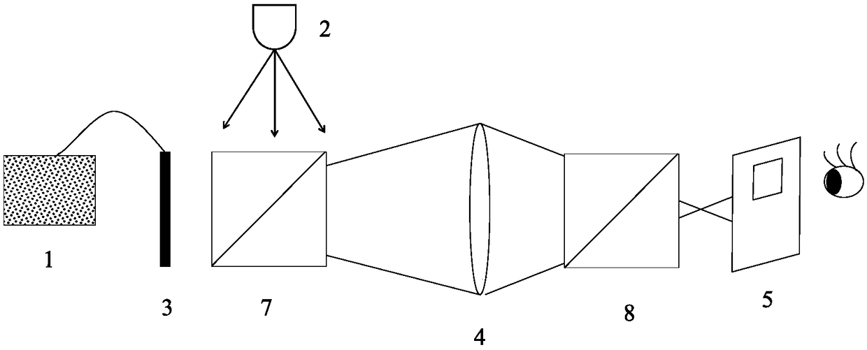
[0085] use image 3 The structure shown results in a display system. That is, the computer 1 is connected to the reflective phase-type spatial light modulator 3 through a data line, and the reflective phase-type spatial light modulator 3, the second beam-splitting prism 7, the lens 4, the first beam-splitting prism 8, and the filter diaphragm 5 are arranged in sequence , the point light source 2 is located on the upper part of the second dichroic prism 7 . The relative positions of the above optical elements are set so that the light emitted by the point light source 2 passes through the second dichroic prism 7 and enters the reflective phase-type spatial light modulator 3, and then passes through the second dichroic prism 7, the lens 4, and the first dichroic prism in sequence. 8 and filter aperture 5.

[0086] Point light source 2 adopts LED point light source, which emits green light with a wavelength of about 532 nanometers for projection; phase spatial light modulator 3...


PUM


Abstract

The invention discloses an augmented reality holographic display method based on complex amplitude modulation. The augmented reality holographic display method comprises the following steps: 1) arranging a point light source, a phase type space light modulator, a lens and a filtering diaphragm and enabling light sent by the point light source to sequentially pass through the phase type space light modulator, the lens and the filtering diaphragm; 2) obtaining parameters of a complex amplitude light field; 3) carrying out complex amplitude light field encoding by utilizing a double-phase decomposition complex amplitude modulation method to obtain an encoded pure-phase hologram; 4) transmitting the encoded pure-phase hologram into the phase type space light modulator and emitting after carrying out phase modulation on light waves, sent by the point light source, in the phase type space light modulator, so as to realize overlapping of a reconstructed image and a real scene. According to the method disclosed by the invention, a diffusion speckle problem in holographic imaging, caused by a random phase, can be avoided through the complex amplitude modulation and the image contrast ratio is enhanced; meanwhile, the point light source can be used for illuminating, and field depth and a view angle of imaging are increased.

Description

technical field [0001] The invention relates to a holographic display method, in particular to an augmented reality holographic display method based on complex amplitude modulation. Background technique [0002] Augmented reality technology is to superimpose computer-generated virtual objects, scenes or system prompt information on real-world scenes to enhance users' perception of the real world. With the continuous development of this topic, a series of technologies and products for augmented reality display have emerged. Among them, Microsoft's Hololens is based on the principle of diffractive head-up display, using advanced sensors, miniature high-resolution and high-contrast miniature digital Light Processor Projection (DLP Pico) technology achieves a better augmented reality display effect. However, due to the limitations of technology and devices, there are still some obstacles to realize the real three-dimensional, large viewing angle, and real-time computing augment...

Claims


Application Information

Patent Timeline
Patent Type & Authority Patents(China)
IPC IPC(8): G02B27/01
CPCG02B27/0103
Inventor 祁怡君夏军
Owner 南京芯视半导体有限公司
Learn More