
Machine visual line scanning device and system and inspection vehicle

A technology of machine vision and line scanning, which is applied in the field of scanning detection, can solve the problems that restrict the development of machine vision line scanning system, uneven image brightness, energy dispersion, etc., and achieve the effect of improving brightness, eliminating speckle and improving reliability

Inactive Publication Date: 2019-07-09
上海欣铁机电科技有限公司
View PDF8 Cites 2 Cited by
  • Summary
  • Abstract
  • Description
  • Claims
  • Application Information

AI Technical Summary

Problems solved by technology

[0005] The present invention provides a visual line scanning lighting device, which can solve the problem that the existing machine vision line scanning system is equipped with LED light sources and energy is scattered, so that the brightness of the collected image is uneven and the quality is not high, which restricts the development of the machine vision line scanning system. The problem

Method used


Image

  • Machine visual line scanning device and system and inspection vehicle
  • Machine visual line scanning device and system and inspection vehicle
  • Machine visual line scanning device and system and inspection vehicle

Examples


Embodiment Construction

[0021] In order to make the object, technical solution and advantages of the present invention clearer, the present invention will be further described in detail below in conjunction with the accompanying drawings and embodiments. It should be understood that the specific embodiments described here are only used to explain the present invention, not to limit the present invention.

[0022] The specific implementation of the present invention will be described in detail below in conjunction with specific embodiments.

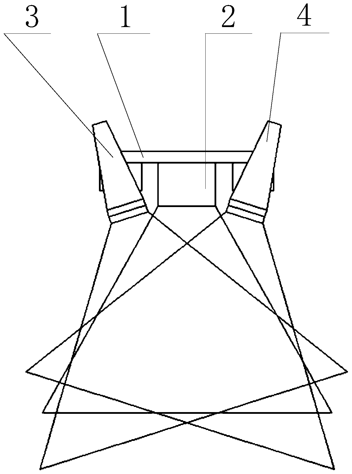
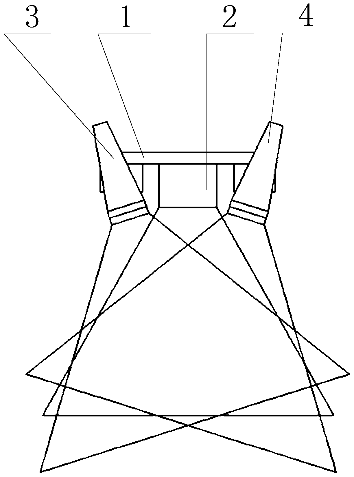
[0023] Such as figure 1 As shown, it is a schematic structural diagram of a machine vision line scanning device provided by an embodiment of the present invention, including:

[0024] The installation part 1 and the line scan camera 2, the first light source 3 and the second light source 4 arranged thereon;

[0025] The installation part 1 is used for installation and fixing of the machine vision line scanning device;

[0026] The line scan camera 2 is arrange...


PUM


Abstract

The invention relates to the technical field of scanning detection, in particular to a machine visual line scanning device and system and an inspection vehicle. The machine visual line scanning devicecomprises an installing part, and a line scanning camera, a first light source and a second light source which are installed on the installing part. The installing part is used for fixedly installingthe machine visual line scanning device. The line scanning camera is installed on the installing part and used for collecting images of a tested object. The first light source and the second light source are arranged on the installing part and can rotate relative to the installing part so that the illumination ranges of the two light sources can at least be partly overlapped. At least part of theoverlapped area is located in the view range of the line scanning camera. By arranging the first light source and the second light source, by adjusting the relative angle of the two light sources, the illumination ranges of the two light sources are overlapped, and therefore speckles are eliminated, the scanning regional brightness is improved, the collected images are clearer, and the detectionreliability is improved.

Description

technical field [0001] The invention relates to the technical field of scanning detection, in particular to a machine vision line scanning device, system and inspection vehicle. Background technique [0002] During the long-term operation management and line maintenance of railway tracks, it is necessary to regularly detect or identify some defects and visible features on the track, including rail welds, cracks on the top surface of rails, skewed and missing fasteners, cracks on track plates, The separation gap of the mortar layer of the track slab, the invasion of foreign objects on the track, the cracks on the inner wall of the tunnel and water stains, etc. [0003] In the field of railway rail transit technology, machine vision line scanning technology has been developing faster and faster. Compared with traditional manual road inspection methods, machine vision line scanning technology is becoming more and more popular due to its fast, accurate and intelligent characteri...

Claims


Application Information

Patent Timeline
Patent Type & Authority Applications(China)
IPC IPC(8): B61K9/10G01N21/95G01N21/01
CPCB61K9/10G01N21/95G01N21/01
Inventor 龚佩毅余佳磊崔瀚钰龚一帆张涛
Owner 上海欣铁机电科技有限公司
Learn More