
Projection laser combining device with application of laser to wide-band light model

A laser beam-combining, wide-band technology, applied in projection devices, optics, instruments, etc., can solve problems such as high cost, poor luminous quality, and inability to eliminate speckle, so as to reduce prices, solve poor luminous quality, and improve luminous quality effect

Pending Publication Date: 2019-08-16
山西莱柏莱特电子科技有限公司
View PDF0 Cites 2 Cited by
  • Summary
  • Abstract
  • Description
  • Claims
  • Application Information

AI Technical Summary

Problems solved by technology

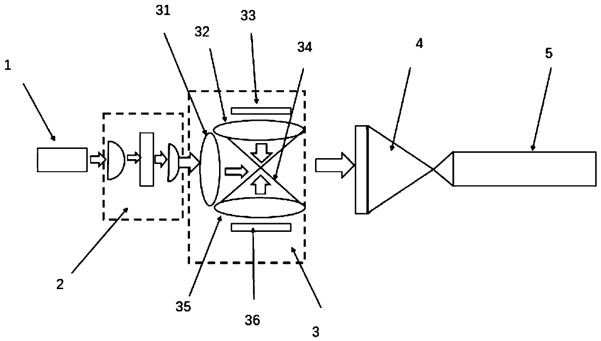
[0005] The purpose of the present invention is to solve the technical problems of poor luminous quality, high cost and inability to eliminate speckles existing in existing laser projection devices, and to provide a laser that can combine broadband incoherent light with laser coupling for broadband applications Projection Laser Beam Combiner for Optical Model

Method used


Image

  • Projection laser combining device with application of laser to wide-band light model
  • Projection laser combining device with application of laser to wide-band light model
  • Projection laser combining device with application of laser to wide-band light model

Examples


Embodiment 1

[0024] Such as figure 1 As shown, a laser in this embodiment is applied to a projection laser beam combining device of a broadband optical model, including a first laser module 1, a first lens group 2, a broadband incoherent light source module 3, Converging lens 4 and homogenizing tube 5, the first laser module 1, first lens group 2, broadband incoherent light source module 3, converging lens 4 and homogenizing tube 5 are sequentially arranged on the first laser In the direction of the outgoing light of the module 1, the first lens group 2 is arranged in front of the outgoing light of the first laser module 1, and the broadband incoherent light source module 3 is arranged at the front of the first lens group 2 In the front, the converging lens 4 is arranged in front of the broadband incoherent light source module 3 , and the uniform light tube 5 is arranged in front of the converging lens 4 .

[0025] The broadband incoherent light source module 3 includes a green light shap...

Embodiment 2

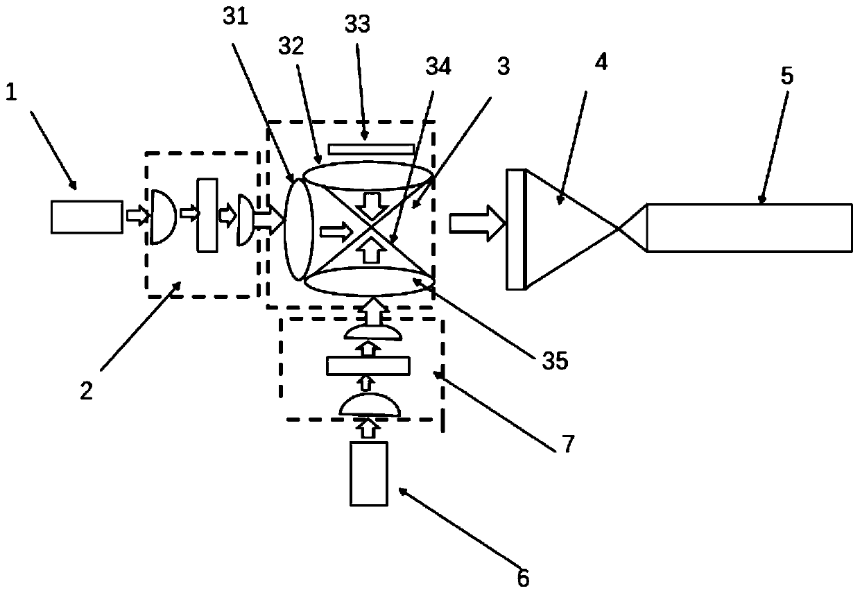
[0029] Such as figure 2As shown, a laser in this embodiment is applied to a projection laser beam combining device of a broadband optical model, and the device includes a first laser module 1, a first lens group 2, and a broadband incoherent light source module 3. Converging lens 4, homogenizing tube 5, second laser module 6 and second lens group 7, the first lens group 2 is arranged in front of the light emitted by the first laser module 1, and the broadband non- The coherent light source module 3 is arranged in front of the first lens group 2, the converging lens 4 is arranged in front of the broadband incoherent light source module 3, and the second lens group 7 is vertically arranged in the broadband incoherent light source module 3, the second laser module 6 is arranged below the second lens group 7, and the uniform light tube 5 is arranged in front of the converging lens 4; the broadband incoherent light source module 3 includes green light Shaping lens 31, red light s...

Embodiment 3

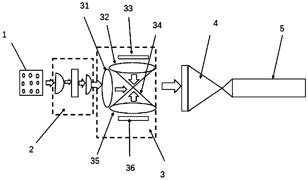
[0033] Such as image 3 As shown, a kind of laser in this embodiment is applied to the projection laser beam combining device of broadband optical model, and the difference from Embodiment 1 is that the first laser module 1 is a green laser dot matrix light source, and the rest The structure is the same as in Example 1.


PUM


Abstract

The invention relates to a projection laser combining device with the application of laser to a wide-band light model, and belongs to the technical field of laser display. The invention aims to solvethe technical problems of poor illumination quality, high cost and no elimination of speckle of an existing laser projection device. The technical scheme is that the device comprises a laser module, alens group, a wide-band incoherent light source module, a converging lens and a light homogenizing tube, the lens group is disposed in front of the light emitted by the laser module, the wide-band incoherent light source module is disposed in front of the lens group, the converging lens is disposed in front of the wide-band incoherent light source module, and the light homogenizing tube is disposed in front of the converging lens.

Description

technical field [0001] The invention relates to a projection laser beam combination device for lasers applied to broadband light models, and belongs to the technical field of laser display. Background technique [0002] As a new type of projection technology, laser projection uses a broadband incoherent light source or laser as a light source. The red, blue, and green lights are combined into white light by a beam combining device, and then transmitted to the projection screen after being integrated by a uniform light tube to complete the project. The whole laser projector shows the process. The main factors affecting the development of projection technology are the price of light source, luminous quality and luminous power of light source. [0003] The pure broadband incoherent light source device or laser array has poor beam quality of the output light source, and cannot satisfy the characteristics of low price and excellent luminous quality at the same time. [0004] As...

Claims


Application Information

Patent Timeline
Patent Type & Authority Applications(China)
IPC IPC(8): G03B21/20
CPCG03B21/208G03B21/2033G03B21/2013
Inventor 赵鹏飞闫杰唐军赵青杨房玲
Owner 山西莱柏莱特电子科技有限公司
Learn More