Steel pipe strong conveyor
A technology of forced conveying and steel pipe, applied in conveyors, mechanical conveyors, transportation and packaging, etc., can solve the problems of poor radial positioning accuracy of workpieces, clamping system impact, limitations, etc., and achieve high radial positioning accuracy, The effect of accurate axis position and strong clamping and conveying force
- Summary
- Abstract
- Description
- Claims
- Application Information
AI Technical Summary
Problems solved by technology
Method used
Image
Examples
Embodiment 1
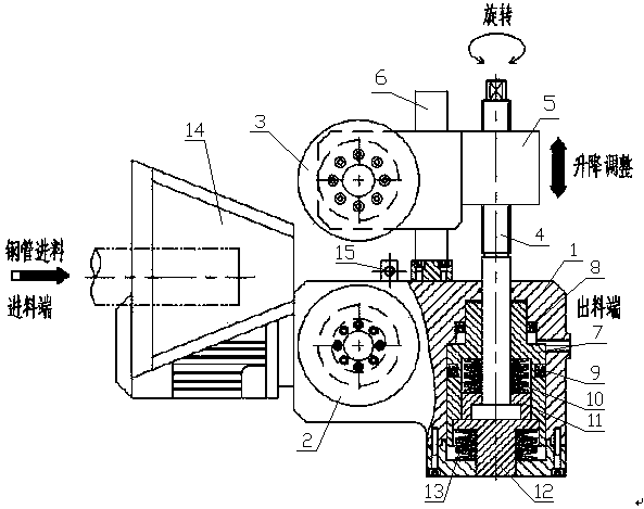
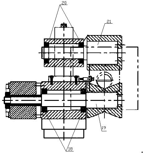
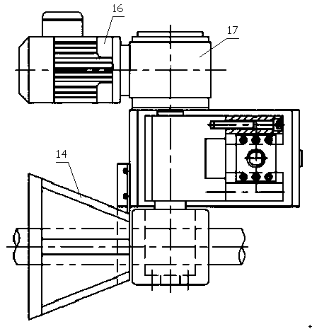
[0019] Example 1, such as figure 1 , figure 2 and image 3 As shown in , the present invention is a steel pipe forced conveying machine, including a machine base 1, a driving wheel 2, a driven wheel 3, a transmission device and a clamping mechanism; the transmission device drives the driving wheel 2 installed on the machine base 1 through a transmission part Rotation; the clamping mechanism is set in the lower cavity of the machine base 1, and the clamping mechanism acts on the lifting screw 4 and the lifting block 5 to limit the position of the driven wheel 3 and generate a pressing force on the steel pipe, while the driven wheel 3 slides It is installed on the rectangular guide rail 6 to generate support, and the rectangular guide rail 6 is fixedly installed on the machine base 1; the driving wheel 2 and the driven wheel 3 work together to generate a conveying clamping force on the steel pipe.
[0020] The invention is a long steel pipe axial feeding conveying equipment, ...
Embodiment 2
[0025] Embodiment 2. On the basis of Embodiment 1, the clamping mechanism is optimally designed. The clamping mechanism is composed of a hydraulic mechanism and an elastic mechanism. The hydraulic mechanism and the elastic mechanism act together on the lifting screw 4 and the lifting block 5. The moving wheel 3 limits the position and generates a pressing force on the conveying steel pipe; the hydraulic mechanism includes a clamping piston 7, a sealing ring A8 and a sealing ring B9; the clamping piston 7, the sealing ring A8 and the sealing ring B9 form a sealed oil chamber; An elastic mechanism is arranged in the cavity of the clamping piston 7; the elastic mechanism includes a butterfly clamping spring group 10, a butterfly spring pressure sleeve 11, a reset pinch 12 and a reset butterfly spring 13; the butterfly clamping spring group 10 passes The butterfly spring pressing sleeve 11 is compressed, and the reset pressure shaft 12 and the reset butterfly spring 13 are preloade...
Embodiment 3
[0026]Embodiment 3, on the basis of embodiment 1 or embodiment 2, the clamping structure of the driving wheel and the driven wheel to the steel pipe is optimally designed, the upper shaft sleeve of the driving wheel 2 is a V-shaped structure, and the driving wheel 2 and the driven wheel 3 pairs of steel pipes form a three-point clamp. The steel pipe is accurately positioned by the driving wheel and the driven wheel, and is driven by the driving wheel for continuous axial feeding.
PUM
 Abstract
Description
Claims
Application Information
 - R&D
- Intellectual Property
- Life Sciences
- Materials
- Tech Scout
- Unparalleled Data Quality
- Higher Quality Content
- 60% Fewer Hallucinations
Browse by: Latest US Patents, China's latest patents, Technical Efficacy Thesaurus, Application Domain, Technology Topic, Popular Technical Reports.
© 2025 PatSnap. All rights reserved.Legal|Privacy policy|Modern Slavery Act Transparency Statement|Sitemap|About US| Contact US: help@patsnap.com


