
Oil-base mud treatment process

A treatment process, oil-based mud technology, applied in water/sludge/sewage treatment, treatment of hydrocarbon oil, petroleum industry, etc., to achieve the effect of thorough treatment, extensive reuse, and improved treatment efficiency and effect

Inactive Publication Date: 2017-06-09
ZHE JIANG ECO ENVIRONMENTAL TECH CO LTD
View PDF5 Cites 20 Cited by
  • Summary
  • Abstract
  • Description
  • Claims
  • Application Information

AI Technical Summary

Problems solved by technology

The amount of chemicals used in this process will promote secondary treatment, and a certain amount of heat energy loss

Method used


Image

  • Oil-base mud treatment process
  • Oil-base mud treatment process
  • Oil-base mud treatment process

Examples


Embodiment 1

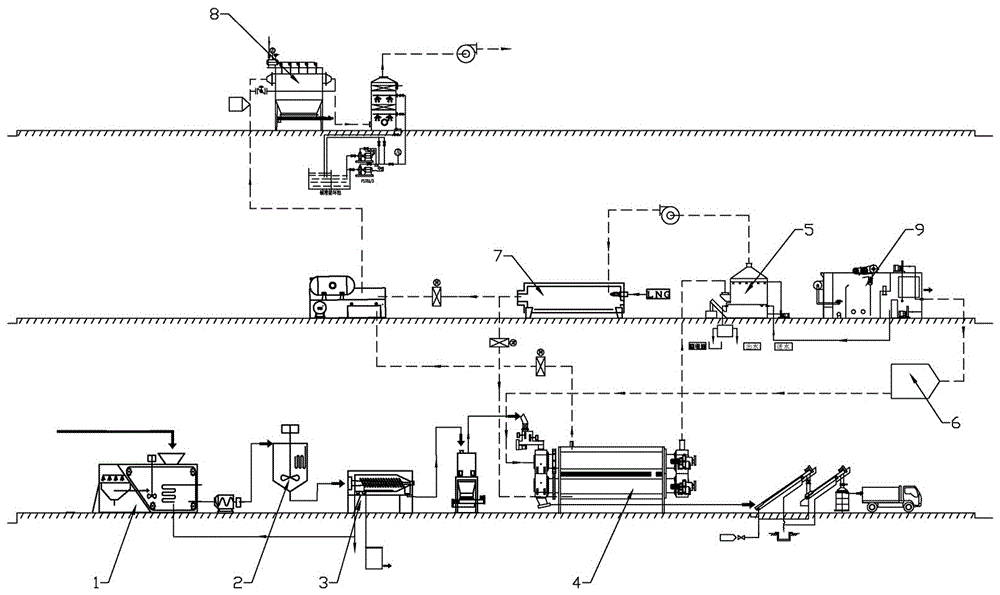
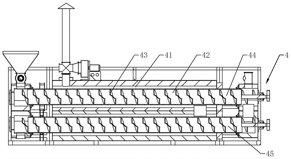
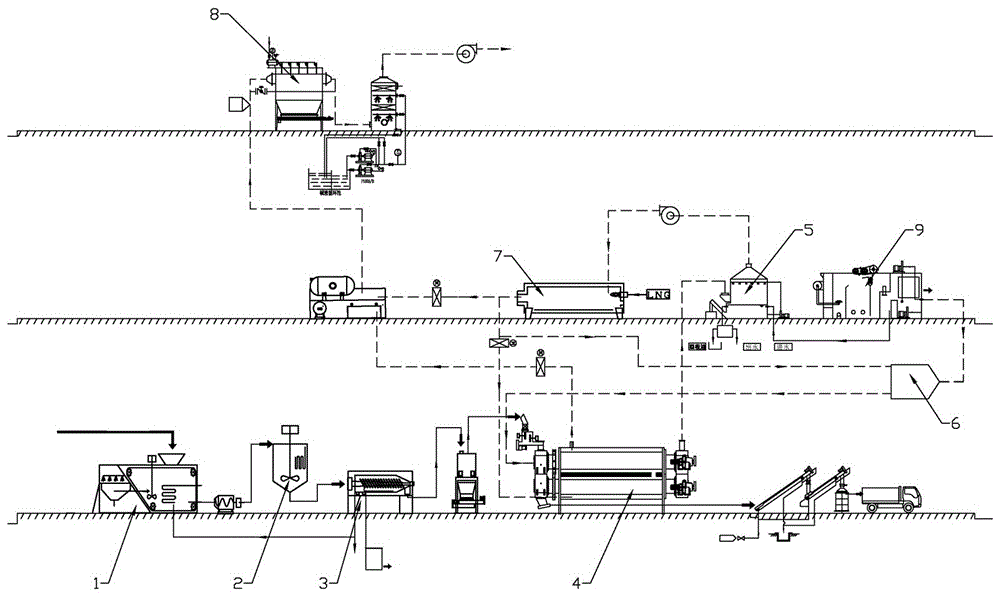
[0042] according to Figure 1 ~ Figure 2 Shown, a kind of treatment process of oil-based mud comprises the following steps:

[0043] aPretreatment: including sorting, tempering and preliminary separation:

[0044] Sorting: The oily sludge is disposed of through the foreign matter separation system 1, which includes a vibrating screen and a hot water injection device to wash away the oil on the surface of sand and gravel, and sort out large particles with a particle size greater than 5mm The impurities are piled up separately, and the liquid oily sludge is sent to the conditioning reaction system 2 after preheating and homogenizing, and the conditioning reaction system 2 can be protected from the influence of feed changes through sorting;

[0045] Conditioning: In the conditioning reaction system 2, the oily sludge is heated to 50-180°C by a heat source, and the sludge is tempered by physical and chemical methods to initially reduce the moisture content of the sludge and reduce ...

Embodiment 2

[0053] The difference from the above-mentioned embodiment 1 is that, according to image 3 As shown, in step d, the heat generated by the combustion of the smokeless combustion device 7 is divided into two parts, one part is used to heat the superheated steam generated by the steam generator 6, and the other part enters the external heating area of ​​the thermal desorption system 4 along with the high-temperature gas 41 for indirect heating.

Embodiment 3

[0055] The difference from the above-mentioned embodiment 2 is that, according to Figure 4 As shown, in the tempering stage in step a, the heat source is provided through the heat exchanger 10, the heat transfer oil is arranged in the heat exchanger 10, and the heat exchanger 10 is arranged between the thermal desorption system 4 and the flue gas treatment system 8, and the heat The tail gas generated by the desorption system 4 heats the heat transfer oil in the heat exchanger 10. During the sorting stage in step a, the heat transfer oil is also passed into the foreign matter sorting system 1 for heating, and the heating temperature is 45°C-90°C.


PUM

PropertyMeasurementUnit
particle diameteraaaaaaaaaa

Abstract

The invention relates to the field of sludge treatment, in particular to an oil-base mud treatment process which includes the steps: a, pretreatment: sorting, tempering and initial separation; b, pyrolysis and desorption; c, condensation and oil-water separation; d, utilization of combustible gas; e, flue-gas treatment. The treatment process adopts an internal and external heating pyrolysis and desorption method and is high in heat effectiveness and complete in treatment effect, a pyrolysis gas heat value is sufficiently utilized in the process, oil and conditioners in oil mud without mechanically separating are thoroughly removed, decomposed macromolecular organic compounds are reserved in an inorganic carbon manner, and final products have wide reuse pathways.

Description

technical field [0001] The invention relates to the field of sludge treatment, in particular to an oil-based mud treatment process. Background technique [0002] With the development of unconventional oil and gas such as shale gas and tight gas, the use of oily sludge has gradually increased. Oily sludge has the advantages of good rheological properties, fluid loss control performance and lubricity, etc. However, during the drilling process, the treatment of oily sludge and cuttings mixture (referred to as oil-based cuttings) produced by the solid control circulation system has become a challenge. Huge environmental problem. During the oily sludge circulation process, vibrating screen machines, desanders, desilters, centrifuges and other equipment will continuously produce a mixture of cuttings and mud of different particle sizes. The mineral oil content exceeds 20%, which belongs to special hazardous waste. The natural environment will lead to serious soil and groundwater...

Claims


Application Information

Patent Timeline
Patent Type & Authority Applications(China)
IPC IPC(8): C02F11/12C02F11/10C10G1/00F23G7/06B01D53/14B01D50/00C10B53/00B09B3/00B09B5/00
CPCB01D53/1456B01D53/1487F23G7/06C10B53/00C10G1/00C02F11/10C02F11/12B09B3/00B09B5/00C10G2300/1003C02F2303/06B09B3/40B01D50/60Y02W10/40
Inventor 车磊赵维维田汪洋
Owner ZHE JIANG ECO ENVIRONMENTAL TECH CO LTD
Learn More