
A gear grinding jig for high-precision quick-change shafts

A high-precision, shaft-based technology, used in gear teeth, gear cutting machines, manufacturing tools, etc., can solve the problems of high fixture cost, low repetitive motion accuracy of the manipulator, affecting processing efficiency, etc., and achieves loose parts positioning benchmark accuracy requirements, which are beneficial to The effect of automatic loading and unloading of robots and reduction of process auxiliary time

Active Publication Date: 2019-08-16
XIAN FASHITE AUTOMOBILE TRANSMISSION CO LTD
View PDF9 Cites 0 Cited by
  • Summary
  • Abstract
  • Description
  • Claims
  • Application Information

AI Technical Summary

Problems solved by technology

[0002] At present, most foreign shaft grinding fixtures are of static pressure expansion wall structure. The manufacturing technology of this structural fixture is difficult, and it is basically monopolized by foreign countries. The cost of the fixture is high, and a single set is more than 100,000 yuan.
Although the structure of the fixture has high clamping precision, the tension gap is small, which is about 1 / 1000 of the clamping diameter. The clamping diameter of our company's shaft parts is 35-45mm, and the clamp tension gap is only 0.035-0.045mm, which requires The dimensional tolerance of the part positioning datum is controlled within 0.025mm, otherwise the part will not be clamped tightly or put in, and the fixture must be disassembled and replaced as a whole when changing production, which is time-consuming and laborious
[0003] Some manufacturers in China use the slotted expansion sleeve structure fixture with the conical surface, and the center positioning adopts the dead top. The clamping gap of this structure is 0.15-0.25mm, and the dimensional tolerance of the part positioning reference is relatively loose, but the clamping gap It is still limited, has poor versatility, and cannot be quickly changed. Moreover, the center dead center cannot guide the loading and unloading of parts. The repetitive movement accuracy of the loading and unloading manipulator is generally low. The position deviation will cause the parts to be misaligned with the positioning holes of the fixture during long-term repeated clamping. If the clamping cannot be done correctly, the machine tool will alarm and stop the automatic production, seriously affecting the processing efficiency

Method used


Image

  • A gear grinding jig for high-precision quick-change shafts
  • A gear grinding jig for high-precision quick-change shafts
  • A gear grinding jig for high-precision quick-change shafts

Examples


Embodiment Construction

[0035] Below in conjunction with accompanying drawing, the present invention is described in further detail:

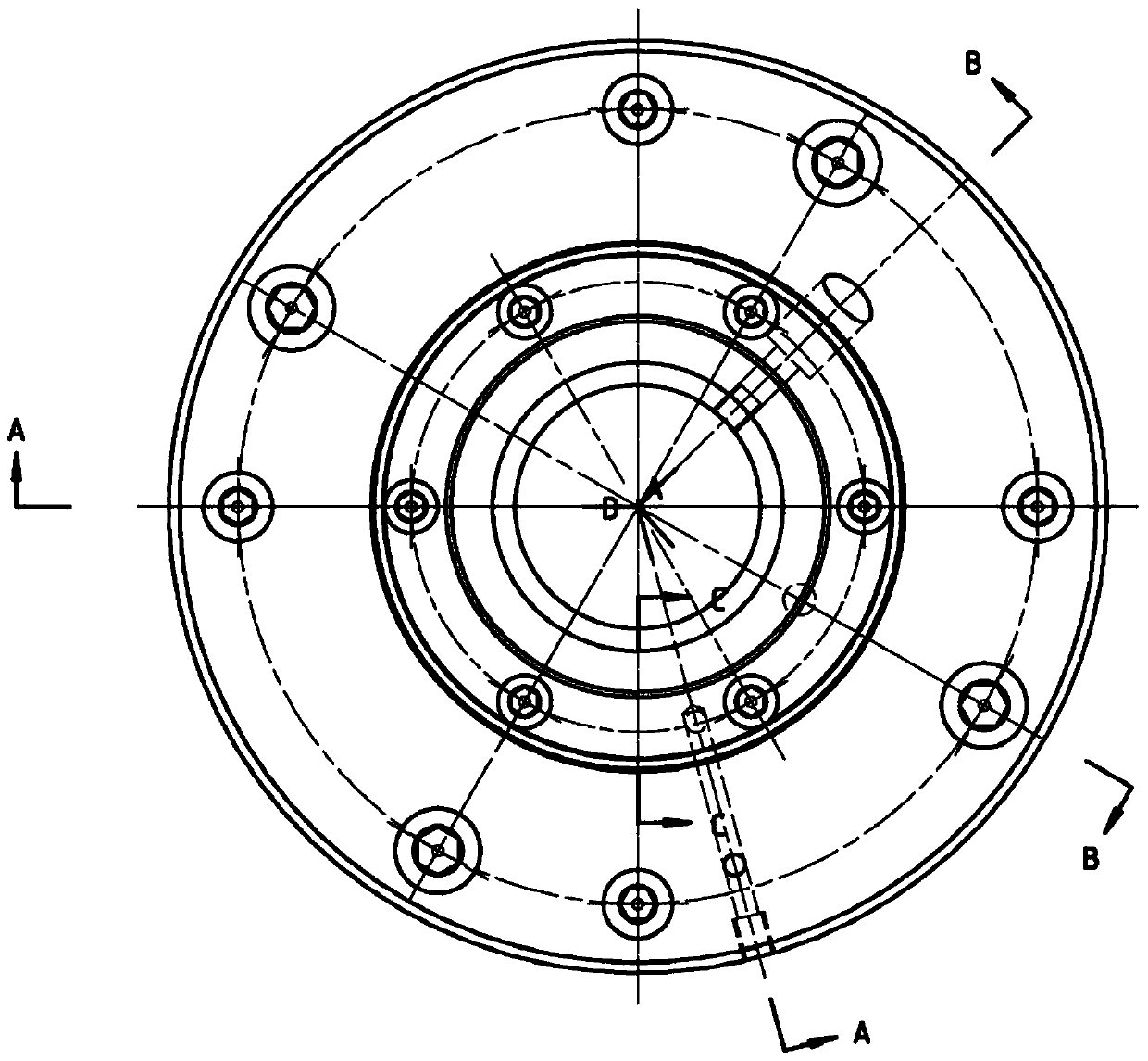
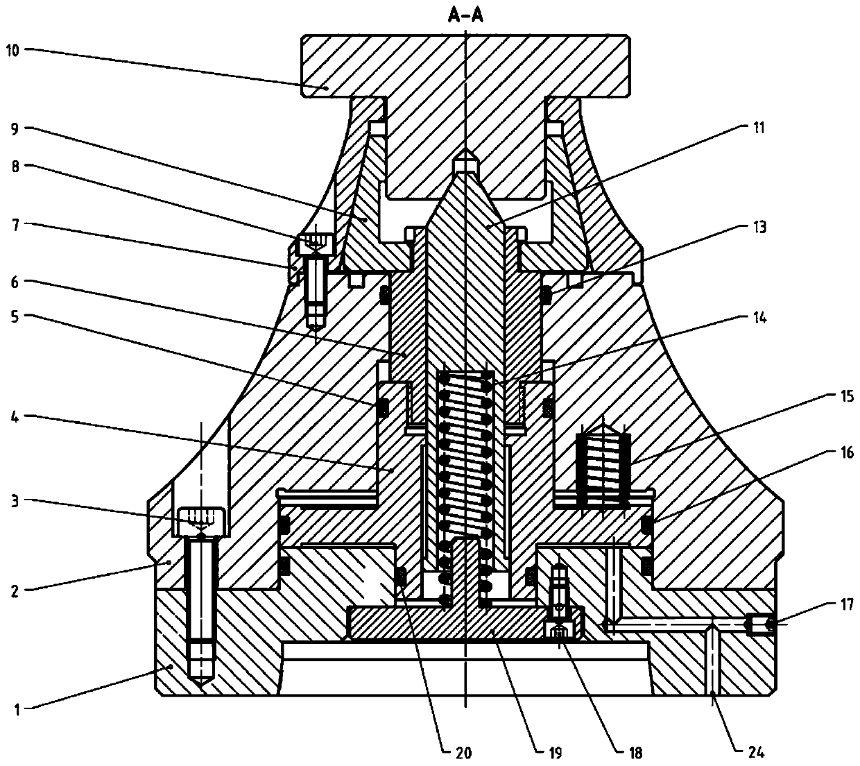
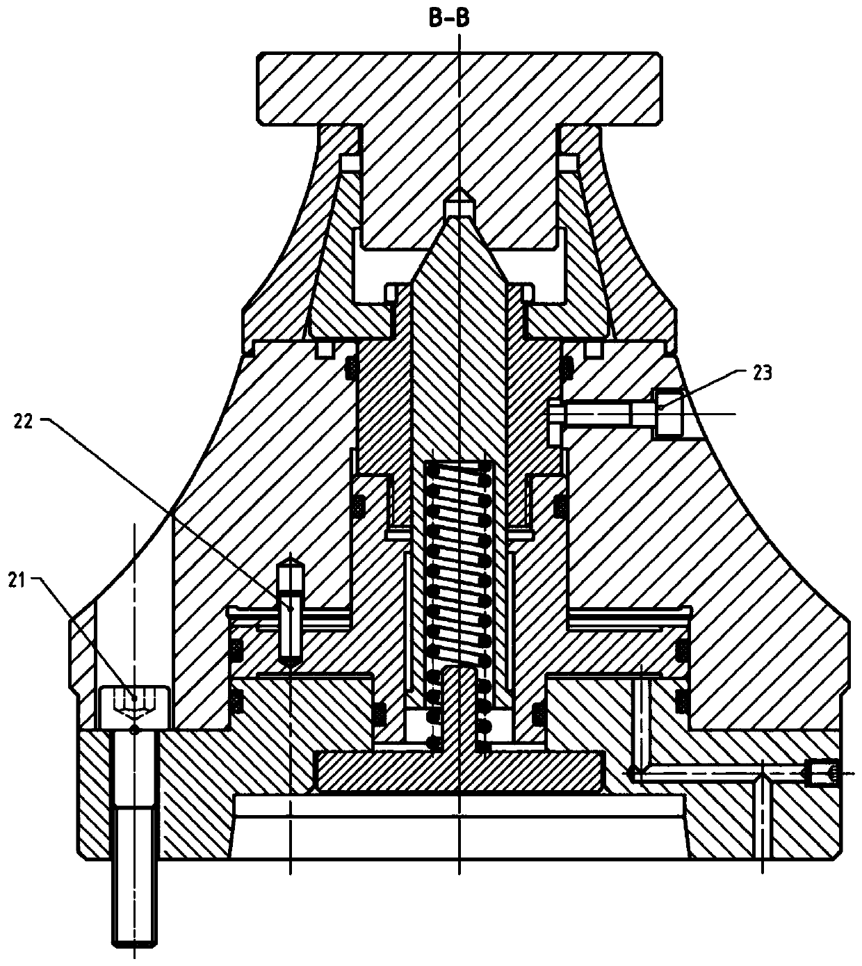
[0036] see Figure 1 to Figure 6 , a gear grinding fixture for high-precision quick-change shafts, including a connecting flange 1 connected to a machine tool, a piston 4 is arranged on the upper side of the connecting flange 1, a tie rod 6 is connected to the upper side of the piston 4, and the upper side of the tie rod 6 The side is connected with an expansion sleeve 9 through a spline, and the expansion sleeve 9 includes a number of diaphragms, and the adjacent diaphragms are bonded by elastic rubber 25, and the internal space of the piston 4 and the pull rod 6 is provided for fixing the workpiece 10. The top 11 of the center, the lower end of the top 11 is provided with an outward first annular protrusion, and the middle part of the piston 4 is provided with an inward second annular protrusion, and the first annular protrusion and the second annular protrusion coo...


PUM


Abstract

The invention discloses a high-precision gear grinding clamp for quickly changing shafts. The high-precision gear grinding clamp comprises a connection flange connected to a machine tool, a piston is arranged on the upper side of the connection flange, the upper side of the piston is connected with a pull rod, and the upper side of the pull rod is connected with an expanding sleeve. A tip for centering a workpiece is arranged in the internal space of the piston and the internal space of the pull rod, a blind hole is formed in the bottom of the tip, a tip spring is arranged in the blind hole, an end cover is arranged on the bottom of the tip spring, and the end cover and the connection flange are fixed. A base is arranged on the outer side of the piston and the outer side of the pull rod in a sleeving manner, the base and the connection flange are fixed, a supporting base is arranged on the outer side of the expanding sleeve in a sleeving manner, the supporting base and the base are fixed, and a flange oil path connected to a gap between the piston and the connection flange is arranged on the connection flange. The high-precision gear grinding clamp can achieve quick product changing, the high-precision gear grinding clamp is provided with the center guiding movable tip which is beneficial to mechanical arm feeding and discharging, the product changing efficiency is improved while the clamping precision is guaranteed, the foreign technological monopoly is broken, and the clamp cost is reduced.

Description

technical field [0001] The invention relates to the field of intermediate shafts of transmissions, in particular to a gear grinding fixture for high-precision quick-change shafts. Background technique [0002] At present, most foreign shaft grinding fixtures are of static pressure expansion wall structure. The manufacturing technology of this structural fixture is difficult, and it is basically monopolized by foreign countries. The cost of the fixture is high, and a single set is more than 100,000 yuan. Although the structure of the fixture has high clamping precision, the tension gap is small, which is about 1 / 1000 of the clamping diameter. The clamping diameter of our company's shaft parts is 35-45mm, and the clamp tension gap is only 0.035-0.045mm, which requires The dimensional tolerance of the part positioning reference is controlled within 0.025mm, otherwise the part will not be clamped tightly or put in, and the fixture must be disassembled and replaced as a whole whe...

Claims


Application Information

Patent Timeline
Patent Type & Authority Patents(China)
IPC IPC(8): B23F23/06
CPCB23F23/06
Inventor 闫鹏辉
Owner XIAN FASHITE AUTOMOBILE TRANSMISSION CO LTD
Learn More