Method and system for realizing circuit ZVS (Zero Voltage Switch) based on delay time

A delay time, circuit technology, applied in electrical components, induction heating, power oscillators, etc., can solve problems such as inability to guarantee circuits, IGBT burnout, occupation, etc.

Active Publication Date: 2017-05-31
HATCO CATERING EQUIP SUZHOU CO LTD
View PDF10 Cites 0 Cited by
  • Summary
  • Abstract
  • Description
  • Claims
  • Application Information

AI Technical Summary

Problems solved by technology

However, it cannot guarantee that the circuit can work at Zero Voltage Switching (ZVS), which will lead to a large capacitance pulse ramp rate (du / dt), and an increase in IGBT (Insulated Gate Bipolar Transistor, insulated gate bipolar transistor) loss.
In some applications, the oscillating circuit is replaced by software synchronization, but this method will occupy more processor resources, and there may be problems such as burning the IGBT when the processor runs away.

Method used


Image

  • Method and system for realizing circuit ZVS (Zero Voltage Switch) based on delay time
  • Method and system for realizing circuit ZVS (Zero Voltage Switch) based on delay time
  • Method and system for realizing circuit ZVS (Zero Voltage Switch) based on delay time

Examples


Embodiment 1

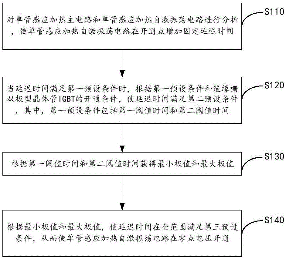
[0056] image 3 A flow chart of a method for implementing circuit ZVS based on delay time provided by Embodiment 1 of the present invention.

[0057] refer to image 3 , the method to achieve circuit ZVS based on the delay time includes:

[0058] Step S110, analyzing the single-tube induction heating main circuit and the single-tube induction heating self-excited oscillation circuit, so that the single-tube induction heating self-excited oscillation circuit increases the delay time at the turn-on point;

[0059] Specifically, it can be seen from the above analysis that adding a fixed delay time can realize full-range load ZVS.

[0060] Step S120, when the delay time satisfies the first preset condition, according to the first preset condition and the turn-on condition of the insulated gate bipolar transistor IGBT, the delay time satisfies the second preset condition, wherein the first preset condition includes The first threshold time Δt and the second threshold time t m ;...

Embodiment 2

[0122] Figure 6 A schematic diagram of a system for realizing circuit ZVS based on delay time provided by Embodiment 2 of the present invention.

[0123] refer to Figure 6 , the system based on the delay time to realize circuit ZVS includes:

[0124] The delay time increaser 100 is used to analyze the single-tube induction heating main circuit and the single-tube induction heating self-excited oscillation circuit, so that the single-tube induction heating self-excited oscillation circuit increases a fixed delay time at the turn-on point;

[0125] The threshold time acquirer 200 is configured to make the delay time satisfy the second preset condition according to the first preset condition and the turn-on condition of the insulated gate bipolar transistor IGBT when the delay time satisfies the first preset condition, wherein the first A preset condition includes a first threshold time Δt and a second threshold time t m ;

[0126] Extremum value obtainer 300, for according...


PUM


Abstract

The invention provides a method and system for realizing circuit ZVS (Zero Voltage Switch) based on delay time. The method comprises the steps of analyzing a single-tube induction heating master circuit and a single-tube induction heating self-exciting oscillating circuit, enabling the single-tube induction heating self-exciting oscillating circuit to increase delay time at a switch point, when the delay time satisfies a first preset condition, enabling the delay time to satisfy a second preset condition according to the first preset condition and a switch condition of an insulated gate bipolar translator IGBT, wherein the first condition comprises first threshold time deltat and second threshold time t <m>; obtaining the minimum value deltat <0> and the maximum value t <m0> according to the first threshold time deltat and second threshold time t<m>; and enabling the delay time to satisfy a third preset condition in a whole range according to the minimum value deltat <0> and the maximum value t <m0>, thereby enabling the single-tube induction heating self-exciting oscillating circuit to switch at a zero voltage. According to the method and the system, the ZVS realization range of the single-tube induction heating self-exciting oscillating circuit is increased, and the cost is reduced.

Description

technical field [0001] The present invention relates to the technical field of oscillation circuits, in particular to a method and system for realizing circuit ZVS based on delay time. Background technique [0002] Single tube induction heating is one of the most common topologies found in induction hobs. Usually, the topology of a single-tube induction heating circuit often uses a self-excited oscillation circuit composed of two open-collector output comparators and a number of capacitors and resistors for peak current control, such as figure 1 shown. The controller only needs to give pulses with a certain duty ratio to make the circuit oscillate. Therefore, from the control point of view, its control method is relatively simple. However, it cannot guarantee that the circuit can work at zero voltage switch (ZeroVoltage Switch, ZVS), resulting in a large capacitance pulse ramp rate (du / dt), and increased loss of IGBT (Insulated Gate Bipolar Transistor, insulated gate bipo...

Claims


Application Information

Patent Timeline
Patent Type & Authority Applications(China)
IPC IPC(8): H05B6/06H03B5/24
CPCH03B5/24H05B6/06Y02B70/10
Inventor 池上洋尼古拉斯·巴锡尔伊山·夏李映芳郭千红
Owner HATCO CATERING EQUIP SUZHOU CO LTD
Why Eureka
Try Eureka