LED device, LED lamp and method for processing conductive bonding wire of LED device
A technology of LED devices and LED chips, which is applied in semiconductor devices, electric solid devices, circuits, etc., can solve the problems of reducing the service life of LED devices, lack of buffering, and damage to conductive bonding wires, so as to eliminate stress impact and enhance firmness performance, reduce the effect of stress shock
- Summary
- Abstract
- Description
- Claims
- Application Information
AI Technical Summary
Problems solved by technology
Method used
Image
Examples
Embodiment 1
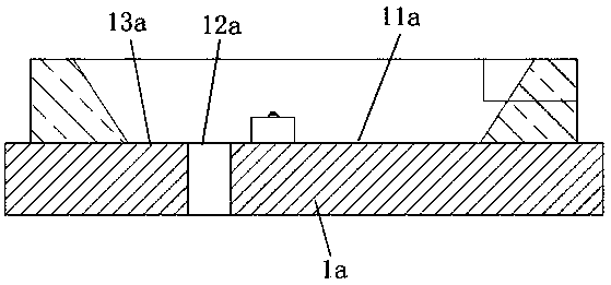
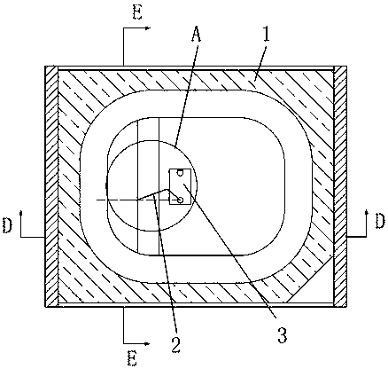
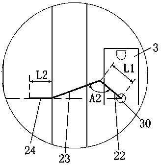
[0051] See attached figure 2 to attach Figure 8 , the invention discloses an LED device, comprising an LED chip 3, a bracket 1 for carrying the LED chip 3, a conductive bonding wire 2 connecting the LED chip electrode 30 and the bracket 1, and covering the LED chip 3 and the conductive bonding wire 2. The encapsulant of the line 2, the encapsulant is preferably silicone resin, silicone or epoxy resin, the support 1 includes an insulating area 12 and the first electrical connection area 11 and the second electrical connection area 11 located on both sides of the insulating area 12, respectively. In the connection area 13 , the LED chip 3 is mounted on the first electrical connection area 11 , one end of the conductive bonding wire 2 is located at the LED chip electrode 30 , and the other end is located at the second electrical connection area 13 .
[0052] Wherein, the LED chip 3 is a blue chip, a red chip or a green chip, which can be selected according to requirements. Whe...
Embodiment 2
[0077] Correspondingly, the present invention also discloses an LED lamp, which includes the LED device described in Embodiment 1 of the present invention, and the lamp using the LED device described in the present invention has a long service life.
Embodiment 3
[0079] Correspondingly, the present invention also discloses a method for processing the conductive bonding wire 2 of the LED device described in Embodiment 1, which includes the following steps:
[0080] (1) After the gold ball is welded to the LED chip electrode 30, the welding head moves upward, and the wire clip is released to form the vertical section 21;
[0081] (2) The welding head moves toward the insulation area 12 according to the set trajectory to form the first bending section 22, and further, it can move obliquely upward;
[0082] (3) The welding head is arranged in the direction of the second electrical connection area 13 according to the set track to form the second bending section 23. Further, it can be arranged obliquely downward in the direction of the second electrical connection area, and the second bending section 23 is located in the space between the second electrical connection area 13 and the first bending section 22;
[0083] (4) Horizontal movement...
PUM
 Abstract
Description
Claims
Application Information
 - R&D
- Intellectual Property
- Life Sciences
- Materials
- Tech Scout
- Unparalleled Data Quality
- Higher Quality Content
- 60% Fewer Hallucinations
Browse by: Latest US Patents, China's latest patents, Technical Efficacy Thesaurus, Application Domain, Technology Topic, Popular Technical Reports.
© 2025 PatSnap. All rights reserved.Legal|Privacy policy|Modern Slavery Act Transparency Statement|Sitemap|About US| Contact US: help@patsnap.com


