Heat recovery device

A heat energy recovery and heat absorption technology, applied in heat storage equipment, indirect heat exchangers, heat exchanger types, etc., can solve problems such as low thermal conductivity, damage, inability to withstand industrial radiant heat intensity and environmental conditions for long-term operation , to achieve the effect of improving radiant heat absorption efficiency and thermal shock resistance

Active Publication Date: 2019-03-08
IND TECH RES INST
View PDF6 Cites 0 Cited by
  • Summary
  • Abstract
  • Description
  • Claims
  • Application Information

AI Technical Summary

Problems solved by technology

However, after a short-term heat collection test of 600 hours, the current solar collector panels on the market found that the solar collector panels were damaged due to shape deformation, so they could not withstand the intensity of industrial radiant heat and the environmental conditions of long-term operation.
However, the thermal conductivity of materials with high heat-resistant temperature is usually low, so it is not easy to balance the life of the heat collector plate and the efficiency of heat energy recovery

Method used


Image

  • Heat recovery device
  • Heat recovery device
  • Heat recovery device

Examples


Embodiment Construction

[0063] The detailed features and advantages of the present invention are described in detail below in the embodiments, the content of which is sufficient to enable any person skilled in the art to understand the technical content of the present invention and implement it accordingly, and according to the content disclosed in this specification, the scope of claims and the drawings , any person skilled in the art can easily understand the related objects and advantages of the present invention. The following examples further illustrate the concept of the present invention in detail, but do not limit the scope of the present invention in any way. In addition, the proportional relationship of components in the drawings of this application is only for illustrative purposes, and is not intended to limit the scope of the present invention.

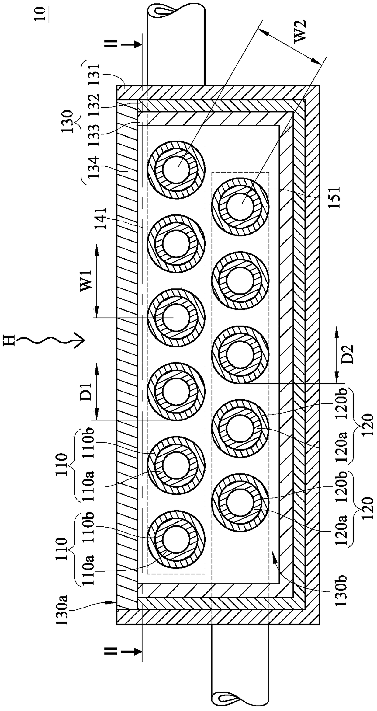
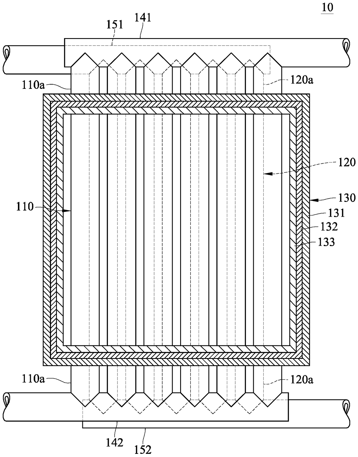
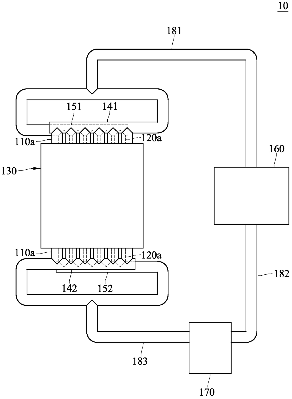
[0064] Please refer to figure 1 , figure 2 and image 3 , figure 1 A partial side cross-sectional schematic diagram of a heat recovery dev...


PUM


Abstract

The present invention discloses a heat recovery device comprising an outer frame, at least a first tube body and at least one second pipe body. The outer frame has a hot penetration side and a containment space. The first tube body is provided in the accommodating space. The first body comprises a first material. The second body is disposed in the containment space. The second tube is away from the heat-through side of the first tube and is axially spaced from the first tube. The second body comprises a second material. The heat resistance temperature of the first material is greater than the heat resistance temperature of the second material. The heat transfer coefficient of the second material is greater than the thermal conductivity of the first material. In the thermal energy recovery apparatus of the present invention, it is possible to prevent the high-intensity radiant heat from causing the first tube to be deformed by the first tube body having a high heat-resistant temperature being disposed closer to the heat-through side, Intensity of radiant heat, the lower intensity of radiant heat can be further absorbed by the second tube with higher heat transfer capability, but can improve the overall radiation heat absorption efficiency.

Description

technical field [0001] The present invention relates to a heat recovery device, in particular to a heat recovery device that absorbs radiant heat. Background technique [0002] Since the Industrial Revolution, people have often obtained energy through combustion to manufacture other products. However, in industrial combustion equipment, in addition to the directly obtained energy, a lot of radiant heat is still generated. At present, the five major domestic industrial radiant heat are metal smelters, glass panel factories, cement plants, petrochemical plants and paper mills. Since the process operation is usually carried out at a temperature of several hundred degrees Celsius to thousands of degrees Celsius, the unused heat energy is mostly dissipated in the environment in the form of heat radiation. [0003] However, traditionally, there is no corresponding recovery mechanism, so these radiant heat is regarded as waste heat that cannot be recovered and reused. For exampl...

Claims


Application Information

Patent Timeline
Patent Type & Authority Patents(China)
IPC IPC(8): F28D20/00
CPCF28D20/00Y02E60/14
Inventor 庄瑞诚张秉宏李天源林育立
Owner IND TECH RES INST
Why Eureka
Try Eureka