Engraving machine with high precision and high stability

A high-stability, high-gloss machine technology, applied in the direction of manufacturing tools, grinding racks, grinding machine parts, etc., can solve the problems of large displacement errors, resonance of the cutter head, and unreachable surface accuracy, etc., to achieve improved Surface accuracy, small driving vibration, and high processing efficiency

Inactive Publication Date: 2017-05-31
东莞市乔扬数控设备有限公司
View PDF10 Cites 5 Cited by
  • Summary
  • Abstract
  • Description
  • Claims
  • Application Information

AI Technical Summary

Problems solved by technology

[0004] The high-gloss machining is mainly processed by the machine head, so the movement accuracy of the machine head will have a great impact on the surface highlight of the product, and the movement of the machine head needs to be very stable to ensure the processing accuracy of the product. Once there is vibration Will have a serious impact on the processing accuracy of the product; but the Z-direction motion substrate of the invention slides up and down through the transmission of the servo motor and the screw mandrel, because when the surface of the product is carried out to high-gloss processing, the moving speed of the spindle cutter head is very high. Fast, using servo motor and screw to drive the displacement accuracy of the spindle cutter head will be difficult to guarantee, and there will be a large displacement error, and the substrate moving in the Z direction is mainly to control the feed amount, and the accurate control of the feed amount It is very important to the processing of the product. When the amount of feed is different each time, the surface accuracy of the product cannot reach a relatively uniform surface accuracy when the product is processed in large quantities, and the drive through the servo motor and the screw will have a relatively high The large vibration makes the machine head very unstable, so that the cutter head will resonate during processing, which will seriously affect the surface accuracy of the product

Method used


Image

  • Engraving machine with high precision and high stability
  • Engraving machine with high precision and high stability
  • Engraving machine with high precision and high stability

Examples


Embodiment Construction

[0021] The present invention will be further described below in conjunction with the drawings:

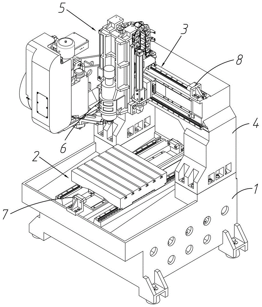
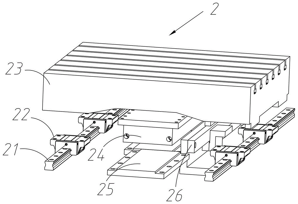
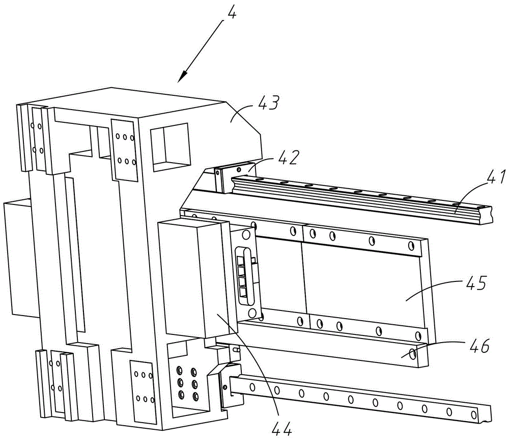
[0022] Such as Figure 1 to Figure 6 Shown is a high-precision and high-stability highlight machine, including a base 1, a Y-axis movement module 2, a gantry 3, an X-axis movement module 4, a Z-axis movement module 5, and a tool head spindle 6. , The Y-axis moving module 2 is installed on the base 1, and the Y-axis moving module 2 includes a Y-direction linear guide 21 installed on the base 1, and a Y-direction sliding guide installed on the Y-direction linear guide 21. Block 22, worktable 23 mounted on the Y-direction slider 22, Y-direction linear motor 24 mounted on the center of gravity of the bottom surface of the worktable 23, Y-direction mounted on the base 1 and matched with the Y-direction linear motor 24 A motor magnetic plate 25 and a Y-direction grating ruler 26 for accurately controlling the moving distance of the worktable, the worktable 23 being driven by the Y-directio...


PUM


Abstract

The invention provides an engraving machine with high precision and high stability. The engraving machine comprises a pedestal, a Y-axis moving module, a portal frame, an X-axis moving module, a Z-axis moving module and a cutter head main shaft. The Y-axis moving module is installed on the pedestal, the X-axis moving module is installed on a cross beam of the portal frame, and the Z-axis moving module is installed on a saddle. The Z-axis moving module comprises a Z-direction sliding block installed on the saddle, a Z-direction linear guide rail installed on the Z-direction sliding block, a Z-axis sliding table installed on the Z-direction linear guide rail, the cutter head main shaft installed on the Z-axis sliding table, a Z-direction linear motor installed at the bottom surface of the Z-axis sliding table, a Z-direction motor magnetic plate installed on the saddle and cooperated with the Z-direction linear motor, a balance cylinder installed on the saddle, and a Z-direction grating ruler. The Z-axis sliding table is driven by the Z-direction linear motor and the Z-direction motor magnetic plate to elevate in the Z axis. A cylinder rod of the balance cylinder is connected with the Z-axis sliding table. The engraving machine is high in machining precision, stable in machining, and long in service lifetime.

Description

Technical field [0001] The invention relates to the technical field of metal surface processing, in particular to a machine for processing a metal surface with a mirror effect. Specifically, it is a high-gloss machine with high precision and high stability. Background technique [0002] The high gloss machine is named according to the characteristics of its processed products. Its appearance is similar to an engraving machine (or a precision carving machine). At present, there are many aliases for the high gloss machine, such as chamfering machine, bright edge machine, chamfering highlight machine, etc. , High-light machines have higher technical requirements, and the requirements for accessories are much higher than those of ordinary engraving machines. [0003] Chinese invention patent 201510568847.4 discloses a high-precision and high-stability high-light machine, including a base, a main body coupling piece is arranged on the base, the main body coupling piece includes a Y-dire...

Claims


Application Information

Patent Timeline
IPC IPC(8): B24B27/00B24B41/02B24B55/00B24B55/06B24B47/04
CPCB24B27/00B24B41/02B24B47/04B24B55/00B24B55/06
Inventor 刘荣
Owner 东莞市乔扬数控设备有限公司
Why Eureka
Try Eureka