
Refrigerator door stamping device with locating groove

A technology of punching device and positioning groove, applied in the field of punching device, can solve the problems of uncomfortable refrigerator door punching, poor buffering effect of punching device, easy deviation of punching, etc.

Inactive Publication Date: 2017-05-24
滁州美业科技股份有限公司
View PDF6 Cites 3 Cited by
  • Summary
  • Abstract
  • Description
  • Claims
  • Application Information

AI Technical Summary

Problems solved by technology

[0003] Patent application publication number: CN 103028660 A proposes a stamping device for positioning and processing workpieces, which includes a fixed assembly, a linkage mechanism, a force application assembly, and a stamping component. The force application assembly is rotatably connected to the fixed assembly. The stamping device It is not suitable for the stamping of refrigerator doors. The positioning effect of the device is not very good. The upper stamping die and the lower stamping die of the existing stamping device are independently separated, so deviations are prone to occur during stamping. The buffering effect of the existing stamping device Not very good, the mold is easy to be damaged, so this invention proposes a refrigerator door stamping device with positioning grooves to solve the above problems

Method used


Image

  • Refrigerator door stamping device with locating groove
  • Refrigerator door stamping device with locating groove
  • Refrigerator door stamping device with locating groove

Examples


Embodiment Construction

[0018] The following will clearly and completely describe the technical solutions in the embodiments of the present invention with reference to the accompanying drawings in the embodiments of the present invention. Obviously, the described embodiments are only some, not all, embodiments of the present invention.

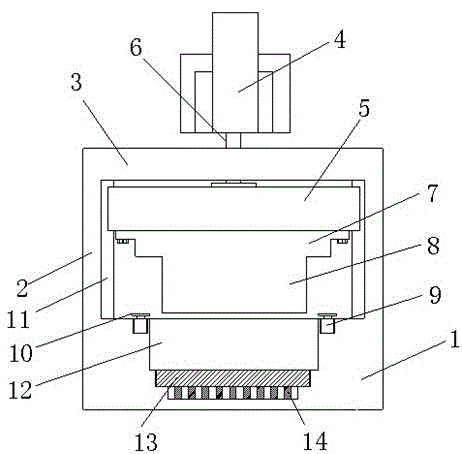
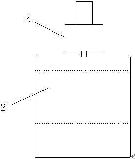
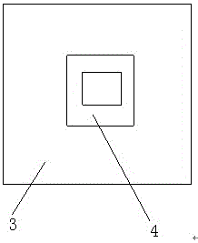
[0019] refer to Figure 1-4 , a refrigerator door stamping device with positioning slots, comprising a base 1, vertically placed support plates 2 are welded on both sides of the top of the base 1, and horizontally placed connecting plates are welded on the tops of the two support plates 2 Plate 3, the inner side walls of the two support plates 2 are welded with vertically arranged slide rails 11, the two slide rails 11 are slidably installed with sliding blocks 5, and the tops of the sliding blocks 5 are welded with connection Rod 6, the connecting rod 6 runs through the top of the connecting plate 3 and extends to the outside of the connecting plate 3, the bottom of...


PUM


Abstract

The invention discloses a refrigerator door stamping device with a locating groove. The refrigerator door stamping device comprises a base; vertically-placed supporting plates are welded on the two sides of the top of the base correspondingly; horizontally-placed connecting plates are welded on the tops of the two supporting plates; vertically-arranged sliding rails are welded on the inner side walls of the two supporting plates correspondingly; sliding blocks are slidably mounted on the two sliding rails; connecting rods are welded on the tops of the sliding blocks; and upper stamping moulds are fixed at the bottoms of the sliding blocks through fastening bolts. The locating groove is formed in the middle of the top of the base; a limiting groove is formed in the bottom of the locating groove; a buffering groove is formed in the bottom of the limiting groove; a plurality of buffering devices are fixed to the bottom of the buffering groove in a rectangular array mode; and a lower stamping mould is mounted in the limiting groove. Through the design of hydraulic cylinders, the impact depth of an impact block can be controlled to adjust the depths of different refrigerator doors, because the needed impact depths for different types of refrigerator doors are not the same.

Description

technical field [0001] The invention relates to the technical field of punching devices, in particular to a refrigerator door punching device with positioning grooves. Background technique [0002] Stamping die is a special process equipment for processing materials (metal or non-metal) into parts (or semi-finished products) in cold stamping processing, called cold stamping die (commonly known as cold stamping die). Stamping is a pressure processing method that uses a mold installed on a press to apply pressure to the material at room temperature to cause separation or plastic deformation to obtain the required parts. For a long time, the development of China's mold industry has been uneven in geographical distribution. The development of the southeastern coastal areas is faster than that of the central and western regions, and the development of the south is faster than that of the north. The most concentrated areas of mold production are in the Pearl River Delta and Yangtz...

Claims


Application Information

Patent Timeline
Patent Type & Authority Applications(China)
IPC IPC(8): B21D22/22B21D43/00
CPCB21D22/22B21D43/003
Inventor 樊徐清付后如祝传强赵东
Owner 滁州美业科技股份有限公司
Learn More