
Guide wire, puncturing device adopting guide wire, and method for using puncturing device

A technology of guide wire and puncture needle, applied in the field of puncture device and guide wire, can solve the problems of serious harm to the health of patients and doctors and low accuracy, and achieve the effect of reducing the danger of X-ray radiation and protecting health

Inactive Publication Date: 2017-05-24
SICHUAN JINJIANG ELECTRONICS SCI & TECH CO LTD
View PDF4 Cites 2 Cited by
  • Summary
  • Abstract
  • Description
  • Claims
  • Application Information

AI Technical Summary

Problems solved by technology

[0007] The purpose of the present invention is to provide a puncture needle that can accurately locate the puncture position and can accurately locate the puncture needle during the operation, aiming at the problems of low accuracy of puncture needle guidance and serious harm to the health of patients and doctors during the operation. A piercing device that protects patients and doctors from X-ray radiation

Method used


Image

  • Guide wire, puncturing device adopting guide wire, and method for using puncturing device
  • Guide wire, puncturing device adopting guide wire, and method for using puncturing device
  • Guide wire, puncturing device adopting guide wire, and method for using puncturing device

Examples


Embodiment 1

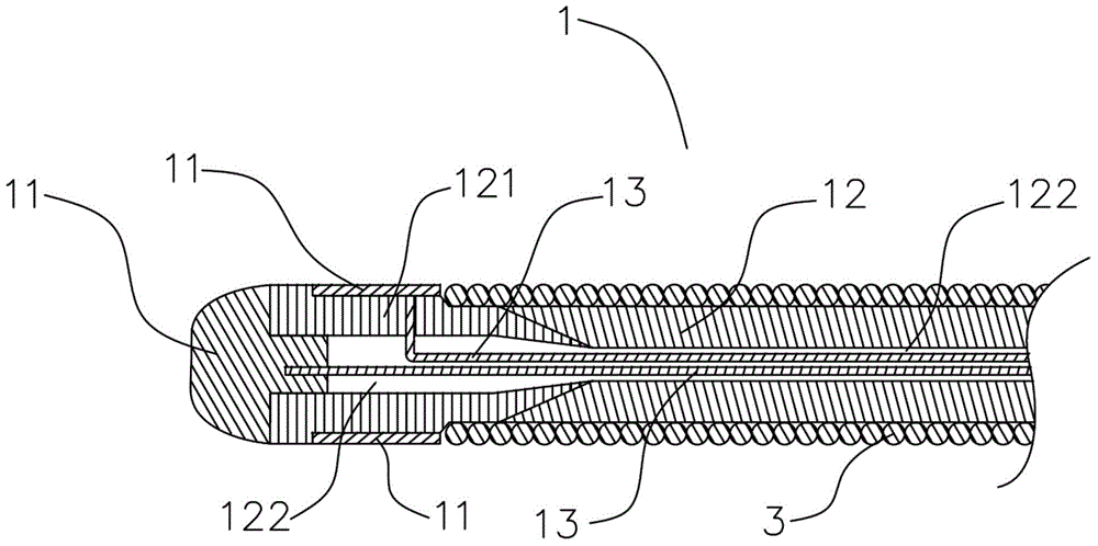
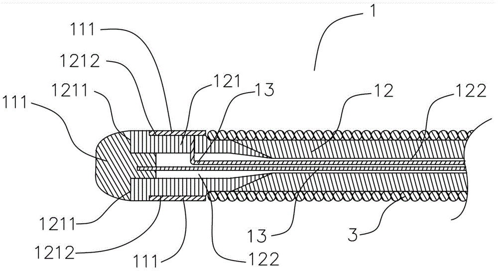
[0082] Such as figure 1 , figure 2 and image 3 As shown, a guide wire 1 includes a support member 12. The end of the support member extending into human tissue is a working end 121, and a signal detection device 11 is arranged on the working end 121. On the signal detection device 11 A wire 13 is connected, and the other end of the wire 13 extends to the outside of the human tissue along the support member and is connected to the signal receiving device 2 , and the signal detection device 11 includes at least one positive electrode 111 .

[0083] In the above scheme of this embodiment, since the working end 121 of the support member 12 is provided with the signal detection device 11, when the working end 121 of the support member 12 extends into the human body, when the signal detection device 11 is immersed in blood or contacts with human tissue, the signal The detection device 11 outputs different signals according to the difference in contact with human tissue, and then...

Embodiment 2

[0085] Such as figure 1 , figure 2 , Figure 4 and Figure 5As shown, in the structure described in Embodiment 1, the signal detection device 11 further includes at least one negative electrode 112 , and the positive electrode 111 and the negative electrode 112 are insulated from each other.

[0086] The signal detection device 11 includes a positive electrode 111 and a negative electrode 112. After the electrodes are energized, since human blood and human tissue are conductors, the signal receiving device 11, the wire 13, the positive electrode 111, the negative electrode 112 and the blood or human body tissue, forming a closed current loop, and because human tissue has different resistivities at different positions, when the signal detection device 11 is at different positions, the signal receiving device 2 can receive different current signals, so it can Based on this, it is determined whether the position of the positive electrode 111 or the negative electrode 112 is a...

Embodiment 3

[0089] Such as Figure 1-3 As shown, in the structure as described in Embodiment 2, the positive electrode 111 is disposed on the end surface 1211 and / or the side surface 1212 of the working end 121 .

[0090] In the above-mentioned solution of this embodiment, the signal detection device 11 has a positive electrode 111, so that when the guiding puncture is performed, when the human body contacts the ground, the human body is equivalent to the ground terminal, that is, the negative electrode, then the signal receiving device 11. A closed current loop is formed between the wire 12, the positive electrode 111, the blood or human tissue and the human body. Moreover, the positive electrode 111 is arranged on the end surface 1211 or the side surface 1212 of the working end, and the signal detected by the signal detection device 11 is the position where the puncture needle is about to pass, which can further improve the performance of the guide wire 1 guiding the puncture needle in ...


PUM


Abstract

The invention relates to the technical field of medical guiding puncturing, in particular to a guide-puncturing device and a using method. The guide-puncturing device comprises a guiding sheathing tube, an expansion tube, a guide wire and a puncturing needle. The guide wire comprises a supporting component. The end, stretching into human tissue, of the supporting component is a working end. A signal detection device is arranged on the working end. A wire is connected to the signal detection device. The other end of the wire extends to the outside of the human tissue along the supporting component and is connected with a signal receiving device. The signal detection device outputs different signals according to different kinds of human tissue with which the signal detection device makes contact, accordingly, whether the position of the signal detection device is a set puncturing position can be determined. Therefore, the puncturing position can be accurately found through the guide wire, the success rate of puncturing can be increased greatly, and pains of patients can be relieved. Meanwhile, dangers of being exposed to X-ray irradiation are greatly reduced for doctors and patients, and therefore the health of doctors and patients is protected while the puncturing needle is positioned and guided accurately.

Description

technical field [0001] The invention relates to the technical field of medical guidance and puncture, in particular to a guide wire, a puncture device using the guide wire, and a method for using the puncture device. Background technique [0002] Atrial septal puncture can be used for transseptal ablation of left accessory pathways, ablation of atrial fibrillation, ablation of left atrial tachycardia, and ablation of left atrium atrial flutter in catheter ablation procedures. Percutaneous catheters cannot be reached antegrade The left atrium needs to be punctured into the left atrium through the atrial septum. The atrial septum is located between the left and right atria. The fossa ovalis is the thinnest part of the atrial septum. Therefore, the fossa ovalis is an ideal location for atrial septal puncture into the left atrium. When puncturing the atrial septum, it is first necessary to determine the location of the fossa ovalis. At present, doctors with rich clinical experi...

Claims


Application Information

Patent Timeline
Patent Type & Authority Applications(China)
IPC IPC(8): A61M25/09A61B17/34
Inventor 邹波李正强朱晓林
Owner SICHUAN JINJIANG ELECTRONICS SCI & TECH CO LTD
Learn More