


Quick Research
Generate reliable direction feasibility study reports for your R&D in just a few steps.

Technical Q&A
Discover and master advanced knowledge NOW. Basics, ideas, possibilities, all at once.

Find Solutions
As an expert in R&D theories, this can generate solutions to your technical problems instantly.

Evaluate Feasibility
Analyze your overall solution with one click, know your potential R&D risks in advance.

Monitor Landscape
Get weekly tech updates, stay abreast of the latest tech innovations and key insights.
Condensation air circulation rear cover plate, condensation air duct system and refrigerator
A rear cover and air circulation technology, which is applied to cooling fluid circulation devices, household refrigeration devices, lighting and heating equipment, etc., can solve problems such as turbulence on the air outlet side, improve heat exchange efficiency, and avoid poor air flow Effect
- Summary
- Abstract
- Description
- Claims
- Application Information
AI Technical Summary
Problems solved by technology
Method used
Image

Examples
Embodiment 1
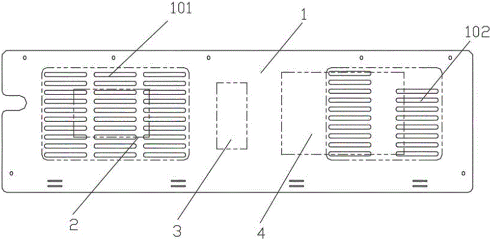
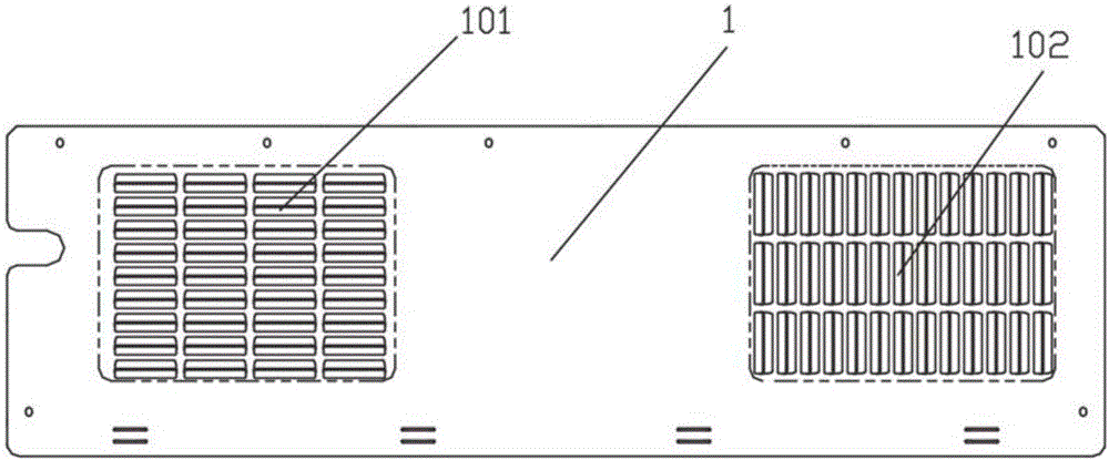
[0031] See figure 2 The condensed air circulation rear cover 1 of the first embodiment includes an air inlet 102 on the air inlet side and an air outlet 101 on the air outlet side.
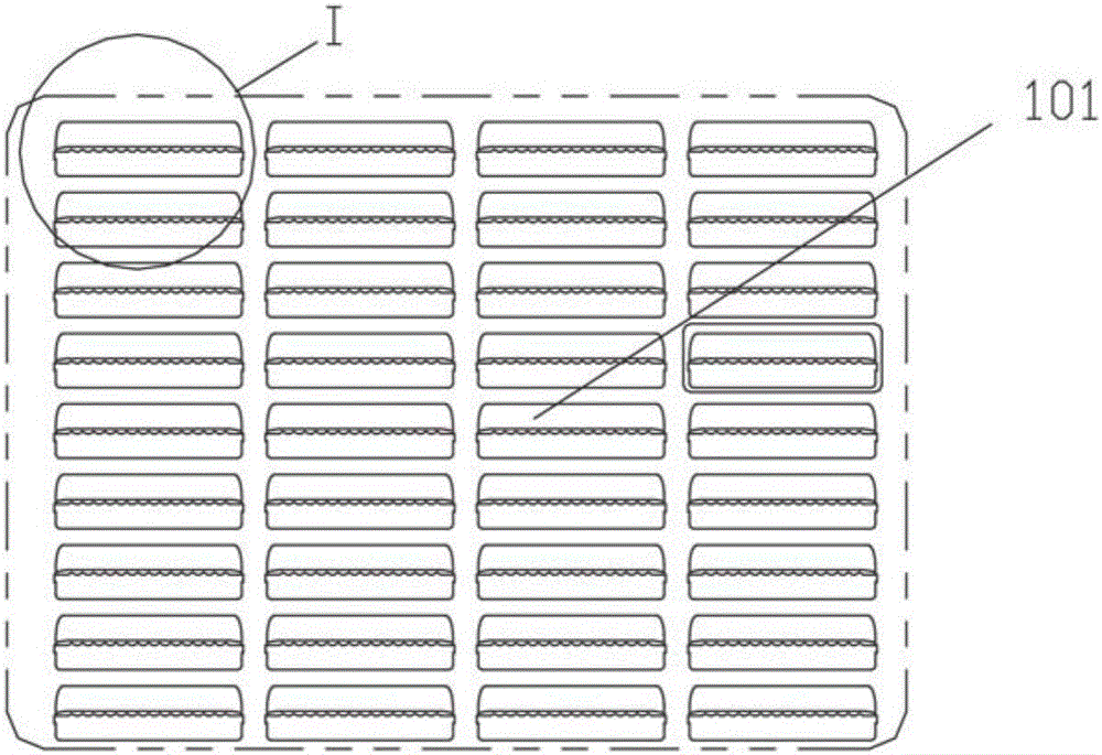
[0032] See image 3 , the air outlet 101 is obtained by punching and flanging, and the edge of the flanging part 103 forms the splitter tooth 104, the tooth shape of the splitter tooth 104, please refer to Figure 4 . It should be noted that the tooth shape of the shunt teeth 104 is not limited by the drawings, and it may also be triangular teeth, rectangular teeth, and crescent shapes.
[0033] In the first embodiment, by setting a split flow structure at the air outlet 101 , it is possible to avoid the problem of poor air circulation caused by turbulence at the air outlet side, thereby effectively improving the heat exchange efficiency of the condenser 4 .
[0034] See Figure 5 In order to further improve the condensation efficiency of the condenser 4, the air inlet 102 of the condensed ai...
Embodiment 2
[0040] The difference between the second embodiment and the first embodiment lies in the structure of the air outlet side, therefore, the second embodiment only describes the structure of the air outlet side. As for the same structure as that of the first embodiment, it will not be repeated here.
[0041] The air outlet 101 of the second embodiment is obtained by punching and flanging, and the flanging portion 103 is formed with flow-distributing ribs extending along the air outlet direction, so that the air outlet 101 is separated by the flow-distributing ribs to form multiple channels. Among them, the formation of multiple channels can avoid the occurrence of disturbances.
[0042] Further, it is preferable that the size of the splitter rib increases gradually along the direction of the air outlet, so that the cross-sectional size of the air flow channel gradually decreases along the direction of the air outlet, thereby better avoiding the occurrence of turbulent flow.
Embodiment 3
[0044] The difference between the third embodiment and the first embodiment lies in the structure of the air outlet side, therefore, the third embodiment only describes the structure of the air outlet side. As for the same structure as that of the first embodiment, it will not be repeated here.
[0045] See Figure 7 In the third embodiment, the flow distribution structure is the flow distribution teeth 104 formed on the edge of the air outlet 101 . The tooth shape of the shunt teeth 104 is also not limited here.
[0046] In the third embodiment, the splitter tooth 104 is directly arranged on the air outlet 101, and the obtained air outlet 101 has a simple structure and is easy to process, which is beneficial to reduce production costs. Of course, the setting of the splitter tooth 104 at the air outlet 101 is not limited by the drawings, and it can also be arranged at the upper edge of the air outlet 101 or at the left and right edge positions of the air outlet 101 according...
PUM
 Abstract
Description
Claims
Application Information
 - R&D Engineer
- R&D Manager
- IP Professional
- Industry Leading Data Capabilities
- Powerful AI technology
- Patent DNA Extraction
Browse by: Latest US Patents, China's latest patents, Technical Efficacy Thesaurus, Application Domain, Technology Topic, Popular Technical Reports.
© 2024 PatSnap. All rights reserved.Legal|Privacy policy|Modern Slavery Act Transparency Statement|Sitemap|About US| Contact US: help@patsnap.com