LED silicon controlled rectifier dimming circuit

A silicon dimming and circuit technology, which is applied in the field of LED thyristor dimming circuits, can solve the problems of low power supply efficiency of LED lighting equipment

Pending Publication Date: 2017-05-10
TCL VERY LIGHTING TECH HUIZHOU CO LTD +1
View PDF8 Cites 0 Cited by
  • Summary
  • Abstract
  • Description
  • Claims
  • Application Information

AI Technical Summary

Problems solved by technology

[0006] Based on this, it is necessary to address the problem of low power supply efficiency of high-power LED lighting equipment, and provide a thyristor dimming circuit that improves power supply efficiency

Method used


Image

  • LED silicon controlled rectifier dimming circuit
  • LED silicon controlled rectifier dimming circuit
  • LED silicon controlled rectifier dimming circuit

Examples


Embodiment Construction

[0039] In order to make the above objects, features and advantages of the present invention more comprehensible, specific implementations of the present invention will be described in detail below in conjunction with the accompanying drawings. In the following description, numerous specific details are set forth in order to provide a thorough understanding of the present invention. However, the present invention can be implemented in many other ways different from those described here, and those skilled in the art can make similar improvements without departing from the connotation of the present invention, so the present invention is not limited by the specific embodiments disclosed below.

[0040] In addition, the terms "first" and "second" are used for descriptive purposes only, and cannot be interpreted as indicating or implying relative importance or implicitly specifying the quantity of indicated technical features. Thus, the features defined as "first" and "second" may ...


PUM


Abstract

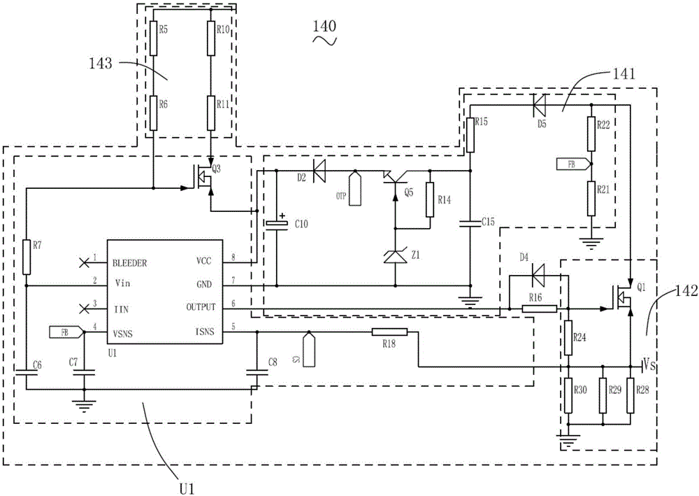
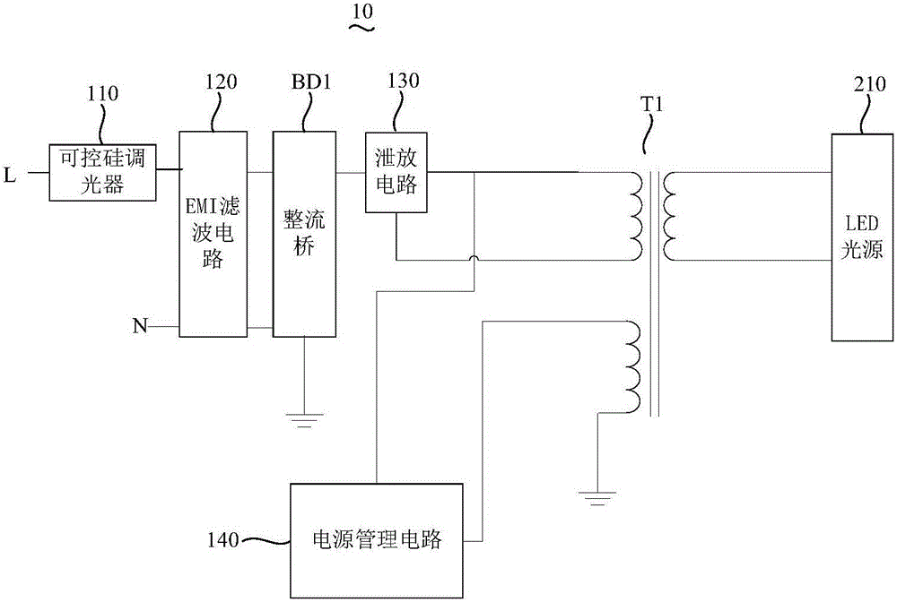
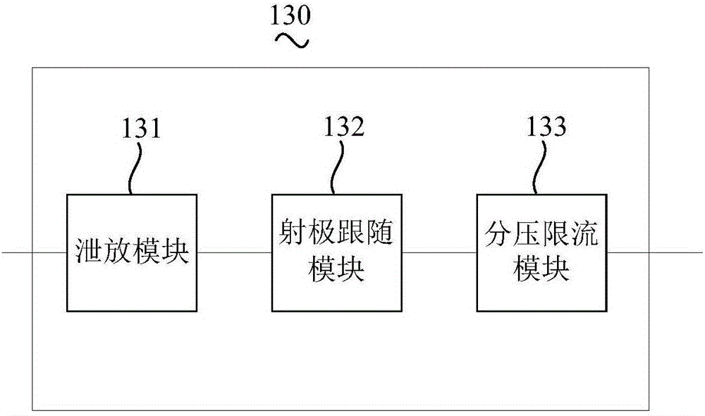
The invention relates to an LED silicon controlled rectifier dimming circuit. The LED silicon controlled rectifier dimming circuit comprises a silicon controlled rectifier dimmer, an EMI filtering circuit, a rectifying bridge, a leakage circuit, a power supply management circuit and a transformer, wherein the output end of the silicon controlled rectifier dimmer is connected with the first input end of the EMI filtering circuit; the EMI filtering circuit is connected with the rectifying bridge; the rectifying bridge is connected with the leakage circuit; two voltage input ends of the leakage circuit are connected with the first end and the second end of a primary winding of the transformer respectively, and the second output end of the rectifying bridge is grounded; the input end of the power supply management circuit is connected with the first end of the primary winding; the power supply end of the power supply management circuit is connected with the first end of an auxiliary winding of the transformer; the second end of the auxiliary winding of the transformer is grounded; and a secondary winding of the transformer is used for being connected with an LED light source. The LED silicon controlled rectifier dimming circuit can be used for high-power LED silicon controlled rectifier dimming illumination equipment; and meanwhile, the LED illumination light-emitting efficiency can be ensured while a condition that the silicon controlled rectifier dimming illumination equipment does not flicker at low luminance can be satisfied.

Description

technical field [0001] The invention relates to the technical field of LED circuits, in particular to an LED thyristor dimming circuit. Background technique [0002] As the fourth-generation lighting source-LED, it has the characteristics of high light efficiency, long life and no pollution. With the advancement of the state's plan to ban the production and use of incandescent lamps, the market penetration rate of LED lighting has gradually increased. [0003] With the advancement of technology, LED lighting products are gradually becoming intelligent, which provides conditions for lamps to achieve secondary energy saving. LED lamps with dimming function are more and more widely used. There are three dimming methods for LED lamps in the market, namely: analog dimming, PWM dimming, and thyristor dimming. Among them, the thyristor dimming circuit is simple and easy to operate, and it is used for dimming LED replacement lamps without changing the original dimming circuit, so ...

Claims


Application Information

Patent Timeline
Patent Type & Authority Applications(China)
IPC IPC(8): H05B33/08H05B44/00
CPCH05B45/37H05B45/00Y02B20/30
Inventor 黄景生钟少强
Owner TCL VERY LIGHTING TECH HUIZHOU CO LTD
Why Eureka
Try Eureka