A magnetic fiber optic coupling device

An optical fiber coupling device and magnetic technology, applied in the field of laser, can solve the problems of easy to wear end face loss, great influence of force, inability to rotate, etc., to achieve fast connection speed, high durability, increased stability and reliability Effect

Active Publication Date: 2019-12-06
尚华
View PDF6 Cites 0 Cited by
  • Summary
  • Abstract
  • Description
  • Claims
  • Application Information

AI Technical Summary

Problems solved by technology

[0004] In view of this, the purpose of the present invention is to provide a magnetic optical fiber coupling device, which solves the problem that the existing coupler needs to be tightly connected by rotating, the coupling efficiency is greatly affected by the number of rotations and force, and the number of connections is large. Afterwards, it is easy to wear the end face, resulting in increased loss, slow connection speed, and inability to rotate after connection.

Method used


Image

  • A magnetic fiber optic coupling device
  • A magnetic fiber optic coupling device
  • A magnetic fiber optic coupling device

Examples


Embodiment 1

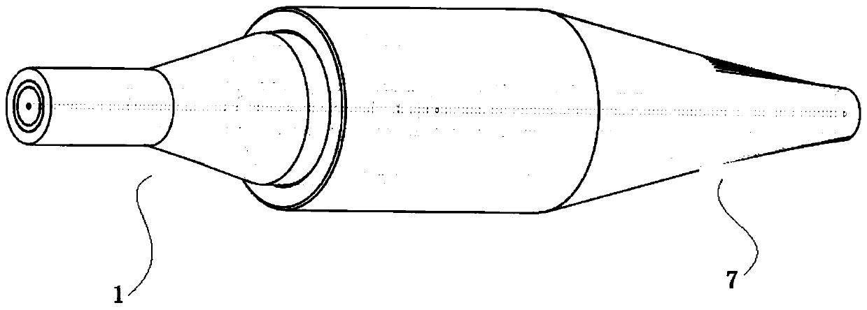
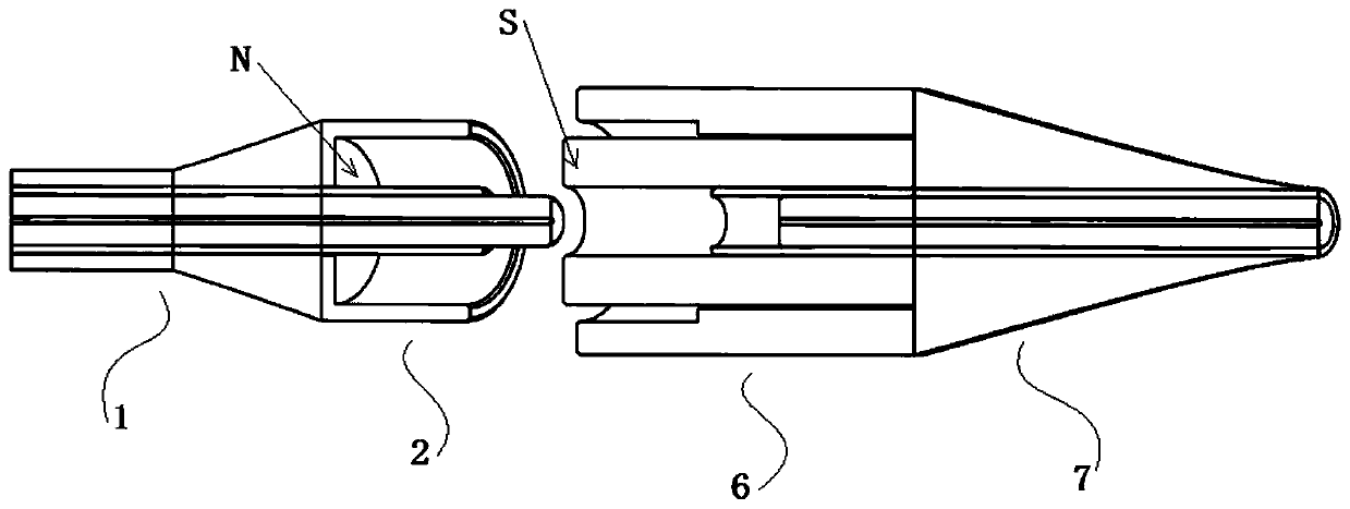
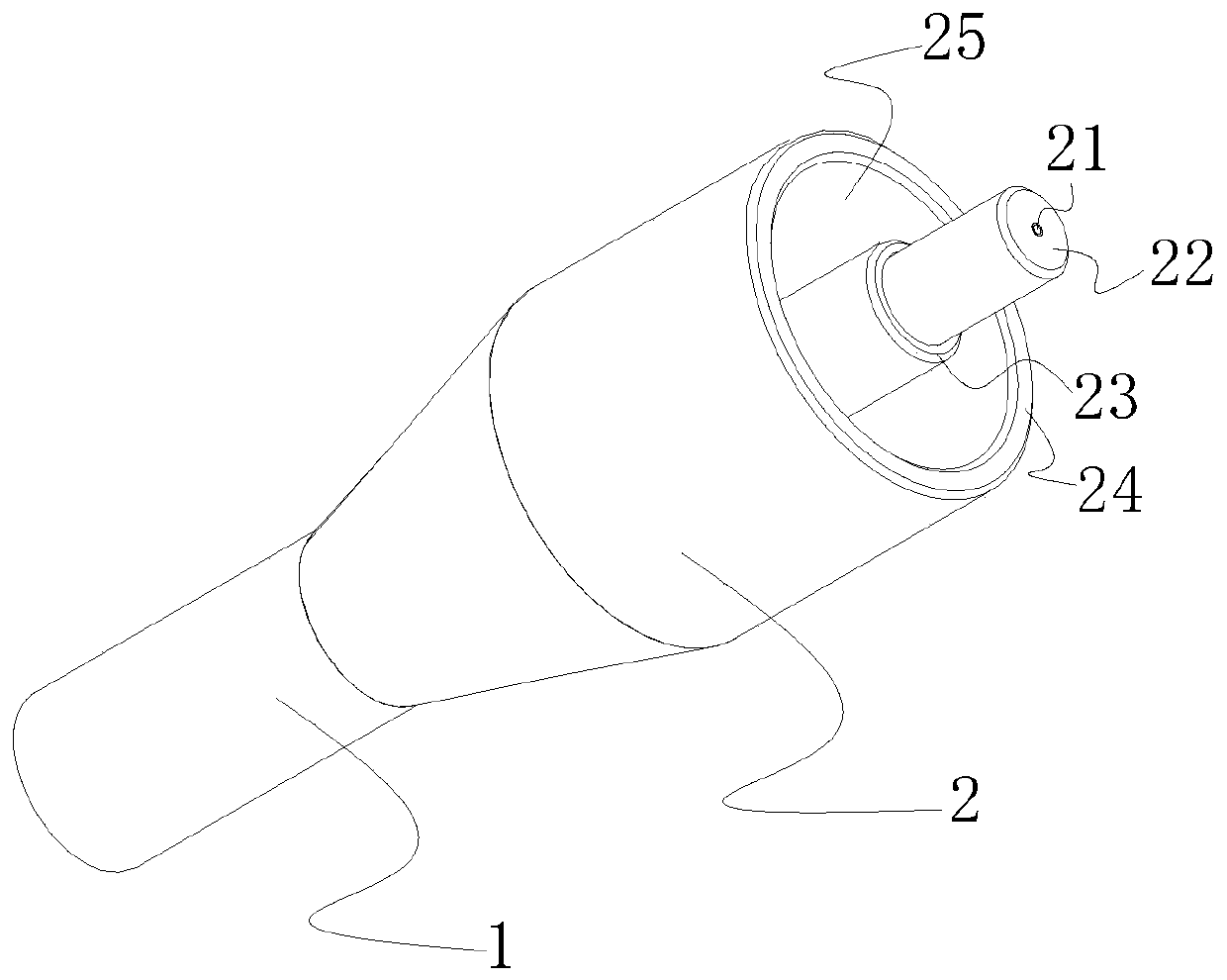
[0040] Such as Figure 1-7 As shown, a magnetic optical fiber coupling device includes a plug and a plug that are inserted into each other. The plug includes a first insertion part 2 and a first connecting part 1 that are fixedly connected to each other. The second plug-in part 6 and the second connection part 7, the free end of the first plug-in part 2 and the free end of the second plug-in part 6 are pluggably connected, and the first plug-in part 2 and the second plug-in part 6 are magnetic and magnetically opposite; the first plug-in part 2 includes a first optical fiber 21 complex and a tube wall 24 arranged outside the first optical fiber 21 complex; the The second insertion part 6 includes a composite body of the second optical fiber 61 and a sleeve disposed outside the composite body of the second optical fiber 61 .

[0041] The magnetism of the first plug-in part 2 and the second plug-in part 6 are opposite so that they can attract each other and the composite of the...

Embodiment 2

[0056] On the basis of Example 1, the method of forming the first plug-in part 2 and the second plug-in part 6 with magnetism can be: using magnetic materials to prepare the first plug-in part 2 and the second plug-in part 2 Two socket parts 6 .

[0057] The magnetic material includes any one of permanent magnetic material (such as NdFeB), soft magnetic material, gyromagnetic material and piezomagnetic material. The permanent magnet material can be NdFeB, such as N52 NdFeB.

Embodiment 3

[0059] On the basis of Example 1, the method of forming the magnetic first plug-in part 2 and the second plug-in part 6 can be: after the first plug-in part 2 and the second plug-in part 6 have been prepared, Electromagnetic magnetization is carried out on the two plug-in parts 6; that is, its magnetism is externally applied.

[0060] The materials for preparing the first plug-in part 2 and the second plug-in part 6 are ceramics, metal or stainless steel, etc., and these materials can be magnetized at a later stage.


PUM


Abstract

The invention relates to a magnetic optical fiber coupling device which comprises an inserting head and an inserting tail which are inserted each other, wherein the inserting head comprises a first plugging part and a first connecting part, the inserting tail comprises a second plugging part and a second connecting part, and both the first plugging part and the second plugging part are magnetic and are opposite in magnetism; the first inserting part comprises a first optical fiber compound body and a tube wall which is arranged out of the first optical fiber compound body; and the second inserting part comprises a second optical fiber compound body and a sleeve which is arranged out of the second optical fiber compound body. The coupler provided by the invention is high in plugging speed, high in durability, good in optical fiber alignment property and high in light conductivity, and can axially rotate randomly after connection without affecting the light conductivity; and by way of inserting or combining each other in a concave-convex manner and the like for matched connection, the stability and reliability of the coupling mode are greatly increased, and the light conductivity is further greatly improved correspondingly.

Description

technical field [0001] The invention relates to the field of laser technology, in particular to a magnetic fiber coupling device. Background technique [0002] Optical fiber coupler is a device for detachable and movable connection between optical fiber and optical fiber. It precisely butts the two end faces of optical fiber so that the optical energy output by the transmitting optical fiber can be coupled to the receiving optical fiber to the maximum extent, and make It intervenes in the optical link so that the impact on the system is minimized. According to the difference of the coupled optical fiber, there are the following classifications: SC fiber coupler: applied to the SC fiber interface, it looks similar to the RJ-45 interface, but the SC interface is flatter, the obvious difference is the contact inside, if It is 8 thin copper contacts, it is RJ-45 interface, if it is a copper column, it is SC optical fiber interface. LC fiber optic coupler: It is applied to LC f...

Claims


Application Information

Patent Timeline
Patent Type & Authority Patents(China)
IPC IPC(8): G02B6/38
CPCG02B6/3825G02B6/3826G02B6/3886
Inventor 尚华吕新杰王智文
Owner 尚华
Why Eureka
Try Eureka