Eureka AIR delivers breakthrough ideas for toughest innovation challenges, trusted by R&D personnel around the world.

Non-oil-sticking fan impeller

A technology for fan impellers and impellers, applied in mechanical equipment, machines/engines, liquid fuel engines, etc., can solve the problems of high maintenance cost of exhaust gas, environmental pollution, long production cycle, etc., to improve value and service life, and to achieve good surface finish , The effect of preventing the surface from sticking

Pending Publication Date: 2017-05-10
林锋
View PDF6 Cites 1 Cited by
  • Summary
  • Abstract
  • Description
  • Claims
  • Application Information

AI Technical Summary

Problems solved by technology

The disadvantage of this method is that it needs to be sequenced, baked twice, the production cycle is long, the painting process is prone to environmental pollution, and the requirements for the protection of occupational diseases and environmental protection are relatively high, which will increase the cost of the enterprise.
[0003] As the surface treatment technology of the first-generation impeller, the above-mentioned first spray coating process once played a certain role in the protection of the impeller. However, with the changes in the market, environmental protection requirements and the development of surface coating technology, this spray The disadvantages of the plastic coating process are obvious
Although the surface treatment technology of the above-mentioned second Teflon baking paint process has a good effect in anti-pollution (non-stick oil), whether the exhaust gas emission in the processing and production process is up to standard, the investment in occupational disease protection and the maintenance cost in the later period are extremely high. High, and the raw material paint has flammable and explosive problems, etc. Therefore, the disadvantages are also obvious

Method used


Image

  • Non-oil-sticking fan impeller
  • Non-oil-sticking fan impeller

Examples


Embodiment 1

[0028] A preparation method for an oil-free fan impeller, comprising the following steps:

[0029] (1) Degrease the workpiece, and then derust and clean the workpiece through sandblasting and metal spraying;

[0030] (2) Then the rust-removed and cleaned workpieces pass through the inner painting line, which automatically removes dust in real time; the workpieces are preheated and then sprayed with primer (nano Teflon), and then dried and cooled after the primer is sprayed; Then spray the intermediate paint (nano Teflon), spray the top coat (nano Teflon), and then go through the high temperature tunnel furnace for sintering and cooling, then check the off-line

[0031] (3) After that, put the workpiece into the outer painting line, spray the outer paint (nano Teflon) after preheating, and then sinter in the high temperature furnace, cool down and check off the assembly line.

[0032] In the step (3), the sintering temperature of the single-layer oily high-temperature exterior...

Embodiment 2

[0034] A preparation method for an oil-free fan impeller, comprising the following steps:

[0035] (1) Degrease the workpiece, and then derust and clean the workpiece through sandblasting and metal spraying;

[0036] (2) Then the rust-removed and cleaned workpieces pass through the inner painting line, which automatically removes dust in real time; the workpieces are preheated and then sprayed with primer (nano Teflon), and then dried and cooled after the primer is sprayed; Then spray the intermediate paint (nano Teflon), spray the top coat (nano Teflon), and then go through the high temperature tunnel furnace for sintering and cooling, then check the off-line

[0037] (3) After that, put the workpiece into the outer painting line, spray the outer paint (nano Teflon) after preheating, and then sinter in the high temperature furnace, cool down and check off the assembly line.

[0038] In the step (3), the sintering temperature of the single-layer water-based exterior paint is ...

Embodiment 3

[0040] A preparation method for an oil-free fan impeller, comprising the following steps:

[0041] (1) Degrease the workpiece, and then derust and clean the workpiece through sandblasting and metal spraying;

[0042] (2) Then the rust-removed and cleaned workpieces pass through the inner painting line, which automatically removes dust in real time; the workpieces are preheated and then sprayed with primer (nano Teflon), and then dried and cooled after the primer is sprayed; Then spray the intermediate paint (nano Teflon), spray the top coat (nano Teflon), and then go through the high temperature tunnel furnace for sintering and cooling, then check the off-line

[0043] (3) After that, put the workpiece into the outer painting line, spray the outer paint (nano Teflon) after preheating, and then sinter in the high temperature furnace, cool down and check off the assembly line.

[0044] In the step (3), the sintering temperature of the two-layer water-based non-stick outer paint...


PUM

PropertyMeasurementUnit
thicknessaaaaaaaaaa
thicknessaaaaaaaaaa
thicknessaaaaaaaaaa

Abstract

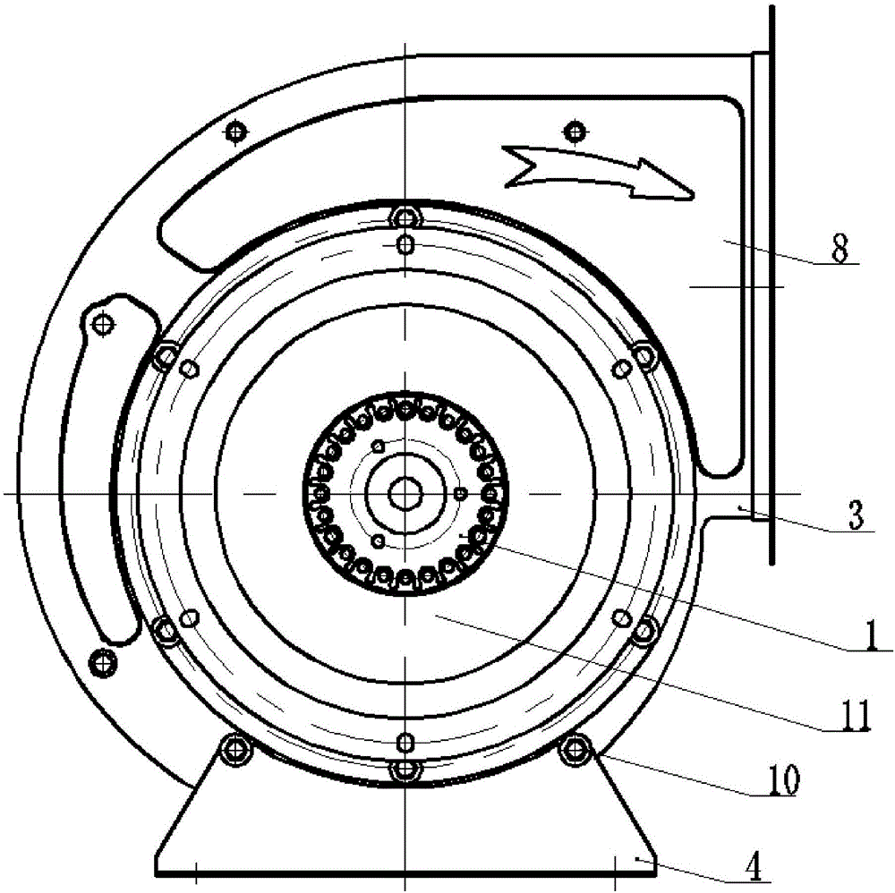
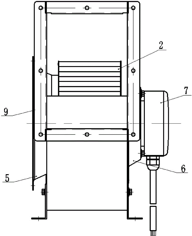
The invention provides a non-oil-sticking fan impeller. The non-oil-sticking fan impeller comprises an impeller, wherein the impeller is installed on an output shaft of a rotor motor; a motor shell is arranged at the outer side of the rotor motor; the motor shell is installed on a housing through a motor fixing plate; an air inlet is formed in the housing at one side of the rotor motor; an air guide plate is installed on the air inlet; an air outlet is formed in one side of the housing; a junction box is installed on the motor fixing plate at one side of the rotor motor; the rotor motor is connected to mains supply through the junction box; and a nanometre Teflon non-sticking layer is arranged at the outer side of the impeller. The non-oil-sticking fan impeller provided by the invention has non-sticking performance such as non-oil-sticking performance, has the advantages of being resistant to wear, corrosion and high temperature, and high in surface smoothness, hardness and smoothness, is capable of being used for a long time in a temperature range from minus 40 DEG C to 300 DEG C and effectively preventing the surface from sticking, and is convenient to clean, thus the value of the product is greatly increased and the service life of the product is greatly prolonged. The non-oil-sticking fan impeller provided by the invention can be widely applied to axial-flow fans and centrifugal fans.

Description

technical field [0001] The invention relates to the technical field of fans, in particular to an oil-free fan impeller. Background technique [0002] In the prior art, there are two methods for the surface treatment of the impeller of the range hood: the first is to spray the surface of the impeller, and its process flow is upper part-ultrasonic degreasing-cleaning-drying-transfer / Upper piece - electrostatic spraying - baking - lower piece. The disadvantages of this method are that it needs to be sequenced, baked twice, the production cycle is long, dust pollution is prone to occur in the processing process, and the requirements for the protection of occupational diseases and environmental protection are relatively high, which will increase the cost of the enterprise. The second is to apply Teflon baking paint to the surface of the impeller. Its technological process is upper part-ultrasonic degreasing-clean water washing-drying-transfer / upper part-painting-baking-lower pa...

Claims


Application Information

Patent Timeline
Patent Type & Authority Applications(China)
IPC IPC(8): F04D29/02F04D29/26F04D25/06F04D29/60B05D7/24B05D3/00
CPCF04D25/0606F04D29/023F04D29/26F04D29/601B05D3/002B05D7/24B05D7/584B05D2506/15B05D2451/00
Inventor 林锋
Owner 林锋
Why Eureka
Eureka Blog
Learn More