
A steel pipe concrete composite support for roadway intersection point

A technology of concrete-filled steel tube and combined support, which is applied in tunnels, tunnel lining, earth drilling and mining, etc., can solve the problems of low support cost and blank application research of concrete-filled steel tube support, and achieves low repair rate in the later period, high cost performance, Reasonable effect of structural design

Active Publication Date: 2018-07-17
SHANDONG JIANZHU UNIV
View PDF4 Cites 0 Cited by
  • Summary
  • Abstract
  • Description
  • Claims
  • Application Information

AI Technical Summary

Problems solved by technology

In the prior art, as a new type of support, the underground pouring concrete-filled steel tube support has the advantages of high bearing capacity and low support cost, but it is limited to the research and application of single roadway support technology, and the deep soft The research on the application of concrete-filled steel tube support in rocky roadway intersections is still blank, so how to better apply this support form in roadway intersections has great research value

Method used


Image

  • A steel pipe concrete composite support for roadway intersection point
  • A steel pipe concrete composite support for roadway intersection point
  • A steel pipe concrete composite support for roadway intersection point

Examples


Embodiment 1

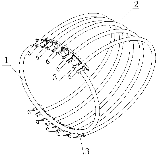
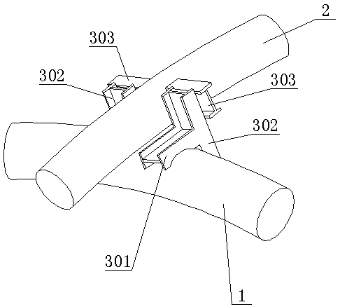
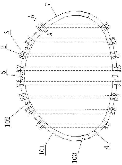
[0042] Such as Figure 1 to Figure 9As shown, the present invention comprises support frame 1, and support frame 1 is the closed structure that connects end to end, is provided with several lap frames 2 at intervals on support frame 1, and lap frame 2 is C shape, and one end of lap frame 2 is positioned at The outer surface of the upper part of the support frame 1 is connected to it through the docking device 3 , and the other end of the splice frame 2 is located on the outer surface of the lower part of the support frame 1 and connected to it through the docking device 3 . The docking device 3 includes a support frame baffle structure and an overlapping frame baffle structure. The support frame baffle structure includes two first baffles 301 welded to the outer sides of the support frame 1 on both sides of the end of the overlapping frame 2, and the two first baffles 301. The distance between a baffle plate 301 is slightly larger than the diameter of the splice frame 2, and t...

Embodiment 2

[0055] Such as Figure 10 ~ Figure 13 As shown, the difference between this embodiment and Embodiment 1 is that it includes a support frame 1, which is a non-closed structure that is not connected from end to end, and several overlapping frames 2 are arranged at intervals on the support frame 1. 2 is n-shaped, one end of the splicing frame 2 is located on the outer surface of the upper part of the support frame 1 and connected to it through the docking device 3, and the other end of the splicing frame 2 is fixed on the roadway floor. The docking device 3 is an insertion sleeve 3001 welded on the upper part of the support frame 1 , and one end of the splicing frame 2 is inserted into the insertion sleeve 3001 to be plugged therewith. Both sides of the socket sleeve 3001 are provided with wing plates 3002 , and the wing plates 3002 are welded on the socket sleeve 3001 and the support frame 1 . Both the support frame 1 and the splice frame 2 are provided with a grouting port 4 a...


PUM


Abstract

The invention relates to a steel pipe and concrete combined bracket used for a roadway junction. The steel pipe and concrete combined bracket comprises a bracket body which is provided with erecting racks connected with the bracket body through butt joint devices. The steel pipe and concrete combined bracket is reasonable in design, high in bearing capacity, easy to construct, low in subsequent repair rate, high in cost performance and capable of being applied to the deep soft rock roadway junction.

Description

technical field [0001] The invention relates to a steel pipe concrete combined support for roadway intersections. Background technique [0002] Roadway is the artery of underground production. According to the requirements of development design and in order to adapt to the change of ore body or the special requirements of geological conditions, roadway intersection points will be arranged. The roadway where two roadways intersect or a roadway bifurcates is called a roadway. Compared with ordinary roadways, the excavation space of roadway intersections is larger, and the design of support body structure and construction technology is more complicated. Roadway intersection is the key part of roadway construction and support. If the design is unreasonable, it will bring great disadvantages to production and safety, especially the disadvantages of intersection support with smaller crossing angles are more serious. The construction method and support method of the intersection p...

Claims


Application Information

Patent Timeline
Patent Type & Authority Patents(China)
IPC IPC(8): E21D11/18E21D11/22
CPCE21D11/18E21D11/22
Inventor 王军王正泽陈冰慧何晓升左建平
Owner SHANDONG JIANZHU UNIV
Learn More