Integrated biofilm reaction system
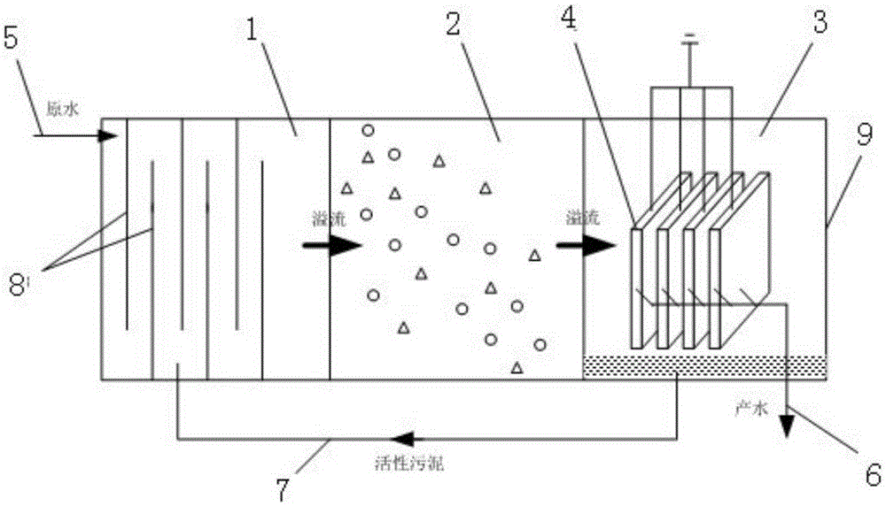
A reaction system and biofilm technology, applied in chemical instruments and methods, water/sewage multi-stage treatment, water/sludge/sewage treatment, etc., can solve the problems of large water consumption and high energy consumption, and achieve energy saving, Small footprint, reduced land occupation and construction costs
- Summary
- Abstract
- Description
- Claims
- Application Information
AI Technical Summary
Problems solved by technology
Method used
Image

Examples
Embodiment 1
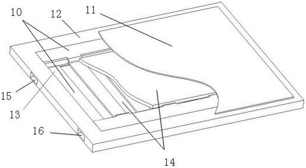
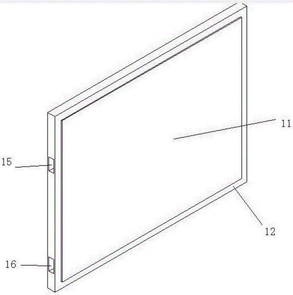
[0051] The sheet metal electrode assembly 10 includes two electrode plates insulated from each other. The electrode plates are sheet metal parts directly cut or stamped on thin metal plates, including a plurality of electrodes arranged in a flat shape and one or more lines connecting all electrodes at the same time. The two electrode plates are stacked alternately, so that the electrode of one electrode plate is placed in the space between two adjacent electrodes of the other electrode plate, and the two electrode plates are connected to different AC power sources through the power adapter 16 provided on the flat frame 12. The output terminal forms an electrode group, which generates a non-uniform electric field around it. The two electrode plates can be both insulated, or one can be insulated and the other can be a bare electrode; when one electrode plate is a bare electrode, the electrode plate should be made of corrosion-resistant materials, or undergo corrosion-resistant tr...
Embodiment 2
[0056] Such as Figure 8 As shown, the difference from Embodiment 1 is that the two electrode plates are grid-shaped electrode plates 22, which are composed of a plurality of electrodes 23 arranged in parallel and two edge lines 24 connecting the two ends of the electrodes. Two grid-shaped electrode plates are stacked at intervals to form an electrode group. Two grid-shaped electrode plates 22 are spaced and stacked with insulating sheets between the side lines 24 . When two grid-shaped electrode plates 22 are overlapped to form a sheet metal DEP electrode structure, the insulating sheet is arranged between the side lines 24 of the two grid-shaped electrode plates 22 to prevent the side lines 24 of the grid-shaped electrode plates 22 from touching , because the two ends of the electrode 23 are connected together by the side line 24, the position of the electrode is relatively fixed during installation, and no later adjustment is required.
Embodiment 3
[0058] Such as Figure 9 As shown, the difference from Embodiment 2 is that the two electrode plates are three-dimensional grid-shaped electrode plates 25, and the three-dimensional grid-shaped electrode plates 25 are composed of a plurality of electrodes 26 arranged in parallel and two side lines 27 connecting the two ends of the electrodes. After the two ends of the electrode 26 are bent toward the same side, they are connected to two side lines respectively. The preferred way is: after the two ends of the electrode 26 are bent in a direction perpendicular to the electrode, then bent 90° in a direction parallel to the electrode 26 to form a ladder shape, so that the middle part of the electrode 26 protrudes relative to the two ends. Such as Figure 10 , Figure 11 As shown, the edge portions of the two three-dimensional grid-shaped electrode plates 25 are stacked at intervals, and the electrodes 26 of the two three-dimensional grid-shaped electrode plates 25 are stacked al...
PUM
 Abstract
Description
Claims
Application Information
 - R&D
- Intellectual Property
- Life Sciences
- Materials
- Tech Scout
- Unparalleled Data Quality
- Higher Quality Content
- 60% Fewer Hallucinations
Browse by: Latest US Patents, China's latest patents, Technical Efficacy Thesaurus, Application Domain, Technology Topic, Popular Technical Reports.
© 2025 PatSnap. All rights reserved.Legal|Privacy policy|Modern Slavery Act Transparency Statement|Sitemap|About US| Contact US: help@patsnap.com