
Method and equipment for manufacturing three-dimensional object

A technology for three-dimensional objects and equipment, which is applied in processing and manufacturing, manufacturing tools, and additive manufacturing. It can solve the problems of large substrate transfer thermal resistance, low heat transfer efficiency, and long heating time, so as to reduce thermal effects and reduce stress. , the effect of improving efficiency

Active Publication Date: 2017-04-19
HUNAN FARSOON HIGH TECH CO LTD
View PDF5 Cites 30 Cited by
  • Summary
  • Abstract
  • Description
  • Claims
  • Application Information

AI Technical Summary

Problems solved by technology

However, the problem is that the infrared radiation heater has a wide range of radiation wavelengths, and the powder has different absorption rates for different wavelengths of radiation, which affects the temperature balance of the powder surface, and the time for the powder material to absorb infrared radiation to the set temperature is longer, which is more due to heating. Due to the low directivity of the device radiation, the working cavity will also heat up due to radiation, thus putting forward higher temperature tolerance requirements for the cavity and the components in the cavity
In the prior art, a heater is installed under the substrate of the laser sintering equipment for manufacturing metal three-dimensional objects to preheat the substrate, and the three-dimensional object is kept warm through the heat conduction of the substrate, but the substrate has a large thermal resistance, low heat transfer efficiency and time-consuming heating longer

Method used


Image

  • Method and equipment for manufacturing three-dimensional object
  • Method and equipment for manufacturing three-dimensional object
  • Method and equipment for manufacturing three-dimensional object

Examples


Embodiment Construction

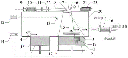
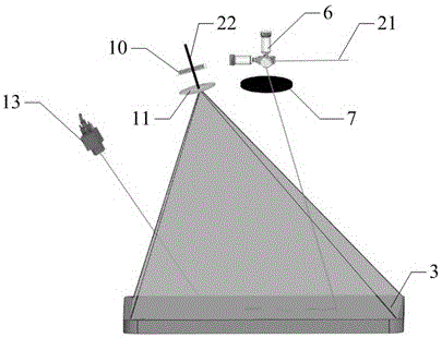
[0037] The following will refer to figure 1 and figure 2 An exemplary apparatus for manufacturing a three-dimensional object and its preheating system according to the present invention are described.

[0038] Such as figure 1 Shown is a specific embodiment of a device capable of implementing the present invention, which is a selective laser melting device. This laser melting equipment has a forming cylinder 17 opening upwards, and a support 2 for supporting a three-dimensional object 19 to be formed is arranged in the forming cylinder 17, and the support 2 can move vertically in the forming cylinder 17 by means of a driving device 14 Move up and down.

[0039] The upper edge of the forming cylinder 17 defines the working plane 5 . A scanning laser 23 is arranged above the working plane 5, which emits a scanning beam 21 and is guided onto the working plane 5 by a scanning deflection mirror 6 for scanning. cross section. There is also a preheating system above the workin...


PUM


Abstract

The invention describes a method for achieving manufacturing of a three-dimensional object by conducting layer-by-layer scanning on a powder layer through an energy bundle. The method comprises the steps that a powder material layer is paved on a base plate or a cured layer, so that the powder layer is formed; part of or more areas of the powder layer are preheated through a preheating light beam, so that the temperature of powder in the preheated areas reaches a set value, wherein setting of the preheating light beam is matched with absorption efficiency of the powder; selective scanning is conducted on the corresponding cross section positions, in the preheated areas, of the three-dimensional object through the energy bundle, and curing of the powder layer is completed, wherein the preheating light beam is a laser beam with the single wave length; and after homogenization is conducted and the light beam uniform in energy distribution is formed and diverged, preheating is conducted on the preheated areas. By means of the method, a powder material adopted in the powder bed additive manufacturing technology can be preheated rapidly and efficiently, and thus the temperature difference generated between the three-dimensional object and the surrounding environment when the three-dimensional object is manufactured is reduced; generation of internal stress is reduced; and manufacturing quality of the three-dimensional object is improved.

Description

technical field [0001] The invention relates to a method and related equipment for manufacturing a three-dimensional object layer by layer through the action of energy beams on powder. Background technique [0002] Common additive manufacturing methods include using energy beams (such as lasers or electron beams) to selectively scan the pavement layer of powder materials, and finally obtain a three-dimensional object through layer-by-layer scanning and solidification accumulation. The scanning position of the energy beam is the corresponding cross-sectional part of the layer of the three-dimensional object to be manufactured. The temperature of the powder material corresponding to this part rises rapidly after the action of the energy beam, and the material is melted instantly and solidified after cooling. After one layer of scanning is completed, continue to spread a new layer of powder on the completed scanning layer, and scan the corresponding cross-section of the new pow...

Claims


Application Information

Patent Timeline
Patent Type & Authority Applications(China)
IPC IPC(8): B29C64/153B29C64/268B22F3/105B33Y10/00B33Y30/00
CPCB33Y10/00B33Y30/00B22F10/00B22F10/322B22F10/366B22F12/13B22F10/28Y02P10/25
Inventor 彭伟鲍光许小曙
Owner HUNAN FARSOON HIGH TECH CO LTD
Learn More