Visual fluorescence labeling technology of silicone rubber filler network structure

A fluorescent labeling and network structure technology, applied in fluorescence/phosphorescence, analytical materials, material excitation analysis, etc., can solve the problem of increasing the complexity of the molecular chain structure of rubber materials, the limitation of research methods and technical means, and the inability to obtain the three-dimensional structure of the sample, etc. question

Inactive Publication Date: 2017-03-22
SOUTHWEAT UNIV OF SCI & TECH
View PDF2 Cites 11 Cited by
  • Summary
  • Abstract
  • Description
  • Claims
  • Application Information

AI Technical Summary

Problems solved by technology

[0002] In the field of filled rubber reinforcement, the reinforcing effect of the filler is not only dependent on some properties of the filler and the rubber itself, but also related to the interaction between the filler and the rubber matrix. The inorganic particles used as fillers are not evenly distributed in the rubber matrix. Instead, a certain network structure is formed according to the different preparation methods. This network structure causes a qualitative change in the mechanical properties of the rubber. However, it is a huge challenge to deeply understand the role of the network structure in the rubber matrix from the physical essence. This is Due to the introduction of the filler network of inorganic particles, the complexity of the molecular chain structure of rubber materials has been further increased, resulting in the limitation of research methods and technical means, making the contribution of the filler network structure to the mechanical properties of rubber and the relationship between structural evolution and mechanical properties unclear. At present, the relationship between the inorganic filler network and its macroscopic mechanical properties is basically limited to some phenomenological descriptions, and there is a lack of ideal experimental techniques for detecting the filler network structure. Therefore, it is necessary to be able to characterize the filler network more simply and intuitively. The technical means of structure can detect its evolution law under the action of stress, and obtain the structure-effect model related to the physical essence, which is conducive to revealing the reinforcement mechanism of inorganic particles
[0003] The current research on the filler network structure in filled rubber, on the one hand, is an indirect description at the theoretical level, mainly including a variety of typical network models, the Payne effect of filler network destruction with strain, and the use of binders to characterize the effect of filler networks on rubber molecules. On the other hand, the traditional electron microscope is used to directly observe the filler network structure, mainly including the use of scanning electron microscope (SEM), transmission electron microscope (TEM), atomic force microscope (AFM) to characterize the filler network microstructure, due to the limitation of SEM penetration ability, Only the morphology and distribution of fillers on the rubber surface can be detected, and the spatial distribution of fillers inside the rubber cannot be studied; although TEM can obtain high-resolution images of the spatial distribution of fillers in rubber, due to the penetration ability of electrons Weak, the sample must be thin enough, so only the filler distribution information in the local area of ​​the sample can be obtained; AFM uses the interaction between the probe and the sample surface to perform micro-area analysis on the three-dimensional topography of the sample surface in a scanning manner A type of microscope is not suitable for analyzing samples obtained by conventional processing methods, and can only be used to analyze the surface morphology of samples, and cannot obtain the three-dimensional structure of samples. Three-dimensional structure is still an unknown world

Method used


Image

  • Visual fluorescence labeling technology of silicone rubber filler network structure

Examples


Embodiment 1

[0018] In the experiment, silicone rubber, self-made silica fluorescent powder and hydroxy silicone oil were added to the internal mixer at a mass ratio of 100:40:8 for uniform mixing. The mixing temperature was 105°C, the speed was 90r / min, and the time was 15min. , and then re-milled for 10 minutes to obtain the rubber compound I; put the rubber compound I at room temperature for 7 days and then mix it with the vulcanizing agent dicumyl peroxide in an internal mixer at a mass ratio of 100:1.69. The mixed rubber II was prepared, the mixing temperature was normal temperature, the rotating speed was 60r / min, and the time was 15min. The flakes of the fluorescent functional silicon rubber composite material are obtained by pressing the tablet.

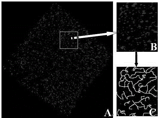
[0019] Then use frozen section technology to obtain slices with a thickness of 0.5 mm, and use laser scanning confocal microscope to scan the sample point by point, line by line, and plane by plane to obtain continuous optical slices. The...

Embodiment 2

[0021] In the experiment, silicone rubber, self-made silica fluorescent powder and hydroxy silicone oil were added to the internal mixer at a mass ratio of 100:60:8 for uniform mixing. The mixing temperature was 105°C, the speed was 90r / min, and the time was 15min. , and then re-milled for 10 minutes to obtain rubber compound I; after placing the rubber compound I at room temperature for 7 days, it was uniformly mixed with the vulcanizing agent dicumyl peroxide in an internal mixer at a mass ratio of 100:1.49, The mixed rubber II was prepared, the mixing temperature was normal temperature, the rotating speed was 60r / min, and the time was 15min. The flakes of the fluorescent functional silicon rubber composite material are obtained by pressing the tablet.

[0022] Using cryosection technology to obtain slices with a thickness of 0.5mm, using a laser scanning confocal microscope to quickly scan the sample point by point, line by line, and plane by plane to obtain continuous opti...

Embodiment 3

[0024] In the experiment, silicone rubber, self-made silica fluorescent powder and hydroxy silicone oil were added to the internal mixer at a mass ratio of 100:40:8 for uniform mixing. The mixing temperature was 105°C, the speed was 90r / min, and the time was 15min. , and then re-milled for 10 minutes to obtain the rubber compound I; put the rubber compound I at room temperature for 7 days and then mix it with the vulcanizing agent dicumyl peroxide in an internal mixer at a mass ratio of 100:1.69. The mixed rubber II was prepared, the mixing temperature was normal temperature, the rotating speed was 60r / min, and the time was 15min. The flakes of the fluorescent functional silicon rubber composite material are obtained by pressing the tablet.

[0025] Using cryosection technology to obtain slices with a thickness of 0.5mm, using a laser scanning confocal microscope to quickly scan the sample point by point, line by line, and plane by plane to obtain continuous optical slices, th...


PUM


Abstract

The invention relates to fluorescence labeling of a silicone rubber filler network, and a visual fluorescence labeling technology thereof. The technology comprises the following steps: first taking homemade rare earth doped silicon dioxide fluorescent powder as the filler by use of an applied patented method of the research group, preparing a silicon rubber composite material with a fluorescence function by use of banburying, vulcanizing and other rubber composite material processing technologies, thereby realizing the fluorescence labeling of the silicon rubber filler network; rapidly scanning the silicon rubber composite material with the fluorescence function point by point, line by line and face by face by use of a laser scanning confocal microscope testing technology to obtain continuous optical sections, and then acquiring a real three-dimensional structure of the silicon rubber filler network by use of a three-dimensional reconstruction computer image processing technology. The visualization of the silicone rubber filler network is realized so as to simply, conveniently, directly and veritably observe the filler network structure and the change process thereof; the technology lays the foundation for developing the research on the structure change and the mechanical property relation of the silicon rubber filler network, and revealing the distortion, damage, reconstruction and the like structure evolution processes of the silicon rubber filler network and the action mechanism of the structure evolution processes to the mechanical property.

Description

technical field [0001] The invention relates to a fluorescent label of a silicone rubber filler network and a visualized fluorescent label technology, belonging to the field of microstructure of rubber composite materials. Background technique [0002] In the field of filled rubber reinforcement, the reinforcing effect of the filler is not only dependent on some properties of the filler and the rubber itself, but also related to the interaction between the filler and the rubber matrix. The inorganic particles used as fillers are not evenly distributed in the rubber matrix. Instead, a certain network structure is formed according to the different preparation methods. This network structure causes a qualitative change in the mechanical properties of the rubber. However, it is a huge challenge to deeply understand the role of the network structure in the rubber matrix from the physical essence. This is Due to the introduction of the filler network of inorganic particles, the co...

Claims


Application Information

Patent Timeline
Patent Type & Authority Applications(China)
IPC IPC(8): G01N21/64
CPCG01N21/643G01N2021/6439
Inventor 康明刘敏牟永仁陈柯旭孙蓉
Owner SOUTHWEAT UNIV OF SCI & TECH
Why Eureka
Try Eureka